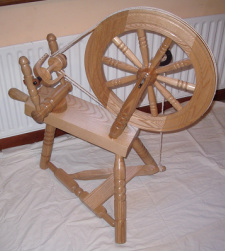
The spinning wheel is quite an advanced woodturning project and will require a large amount of material and will also a lot of time. All turning aspects of this project are relatively straight forward but will require a high level of accuracy in order to ensure all parts fit together tightly. The material selected for this project is ash, however other hardwoods such as mahogany, maple or black walnut would also be suitable.
Project Requirements:
To view how some of the different parts of the spinning wheel are processed please click on the videos below or hover over the photos to read the description given
Project Requirements:
- Hardwood Material
- Lathe and Lathe tools
- Pillar Drill and drill bits
- Engineering Lathe
- Welder
To view how some of the different parts of the spinning wheel are processed please click on the videos below or hover over the photos to read the description given
Below is a video showing the early stages of making one of the legs of the spinning wheel:
Below is a video showing the early stages of completing one of the legs of the spinning wheel:
Below is a video showing the final stages of completing one of the legs of the spinning wheel:
Below are a selection of photos and descriptions of the manufacture of the different parts of spinning wheel:
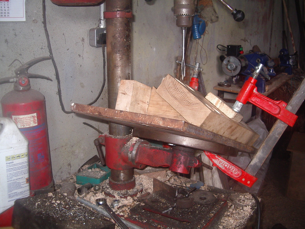
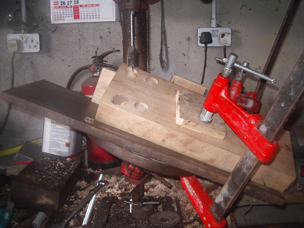
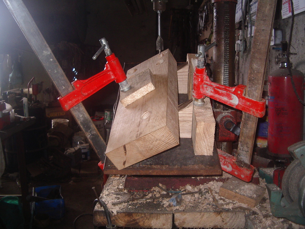
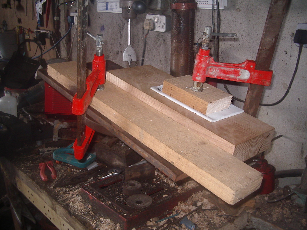
The Base
Here is a photo-log of the steps followed when making the main base piece of the project. The holes for the front two legs were bored by using a jig to achieve the required angle.
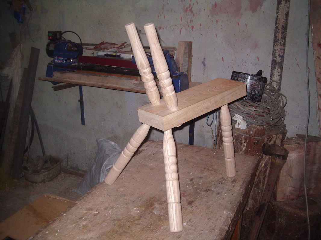
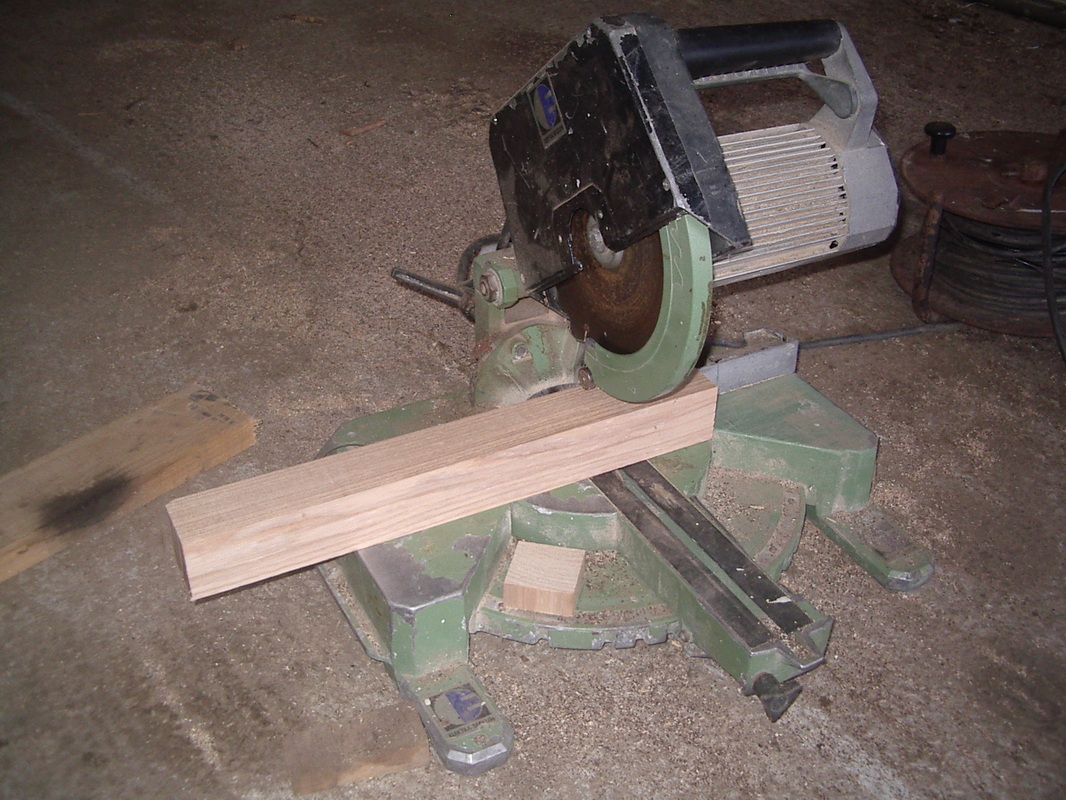
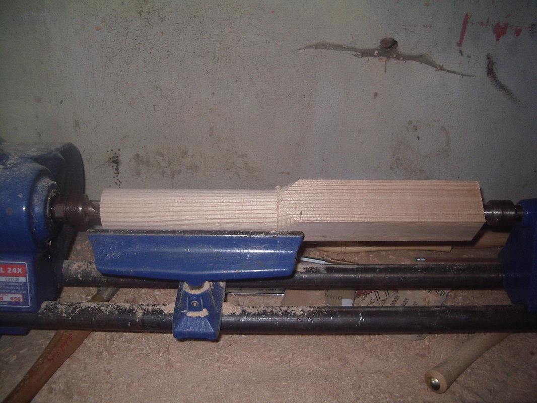
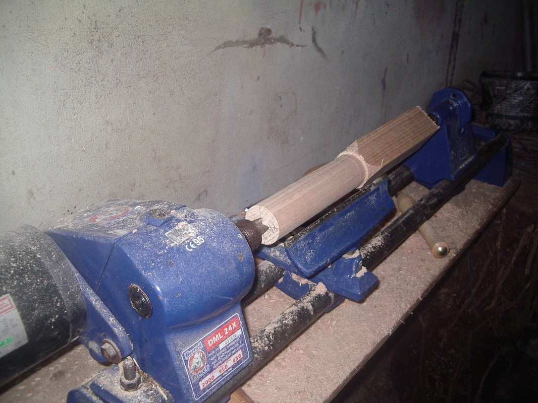
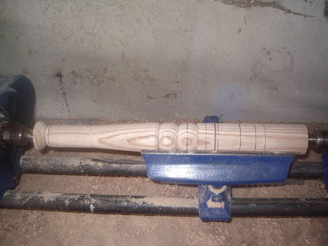
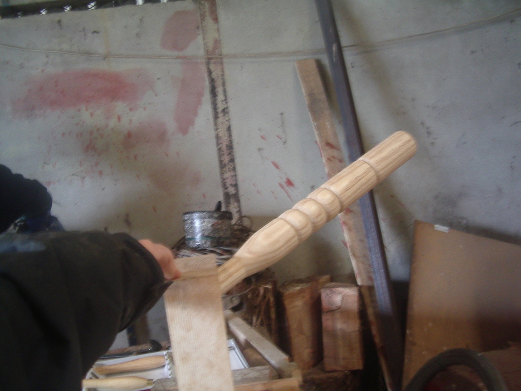
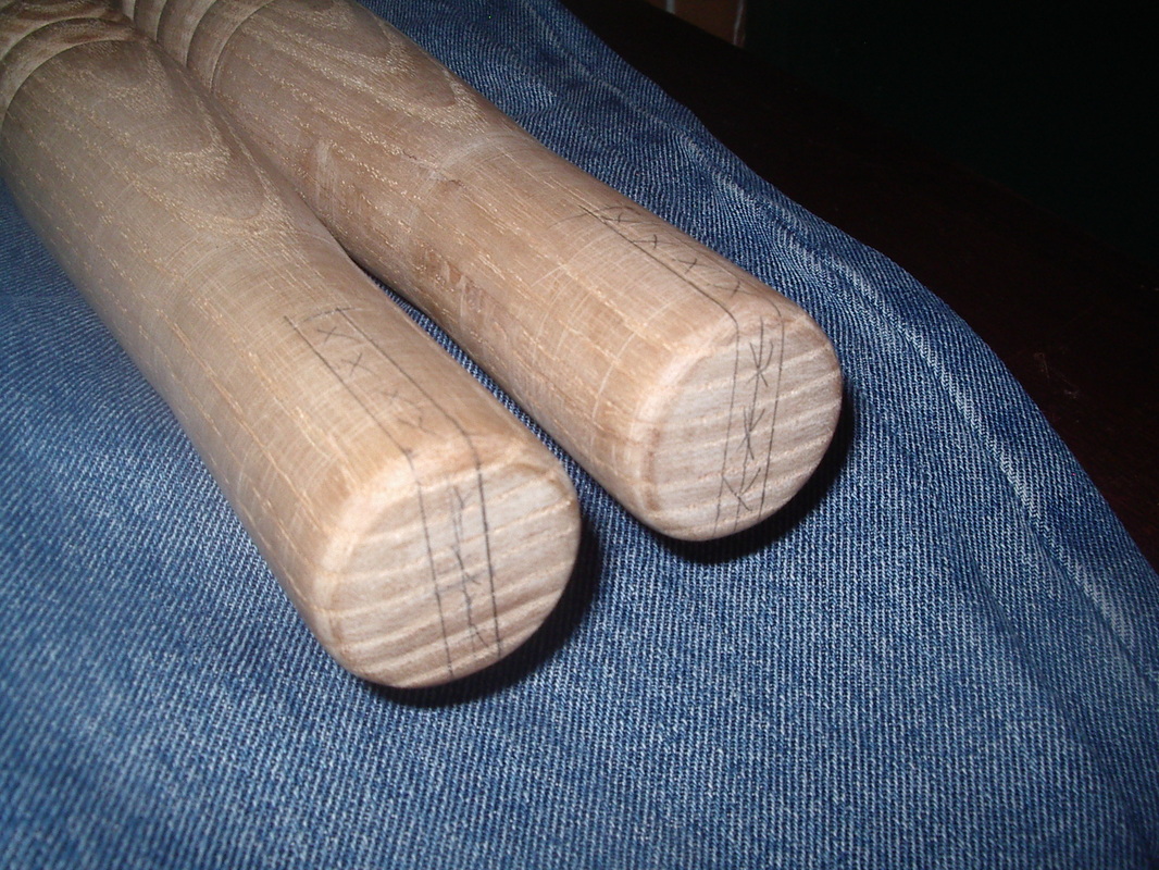
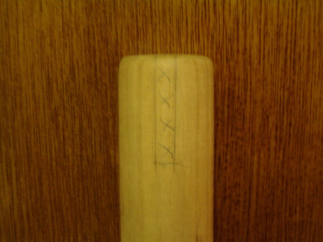
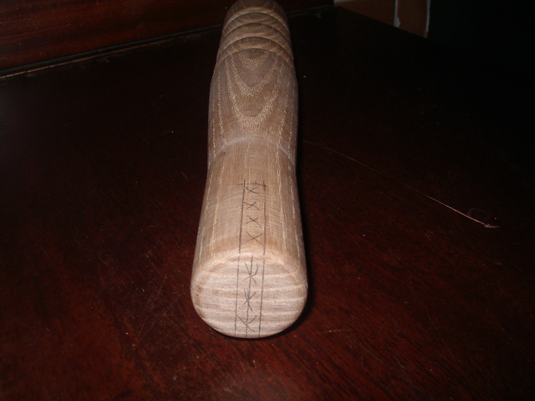
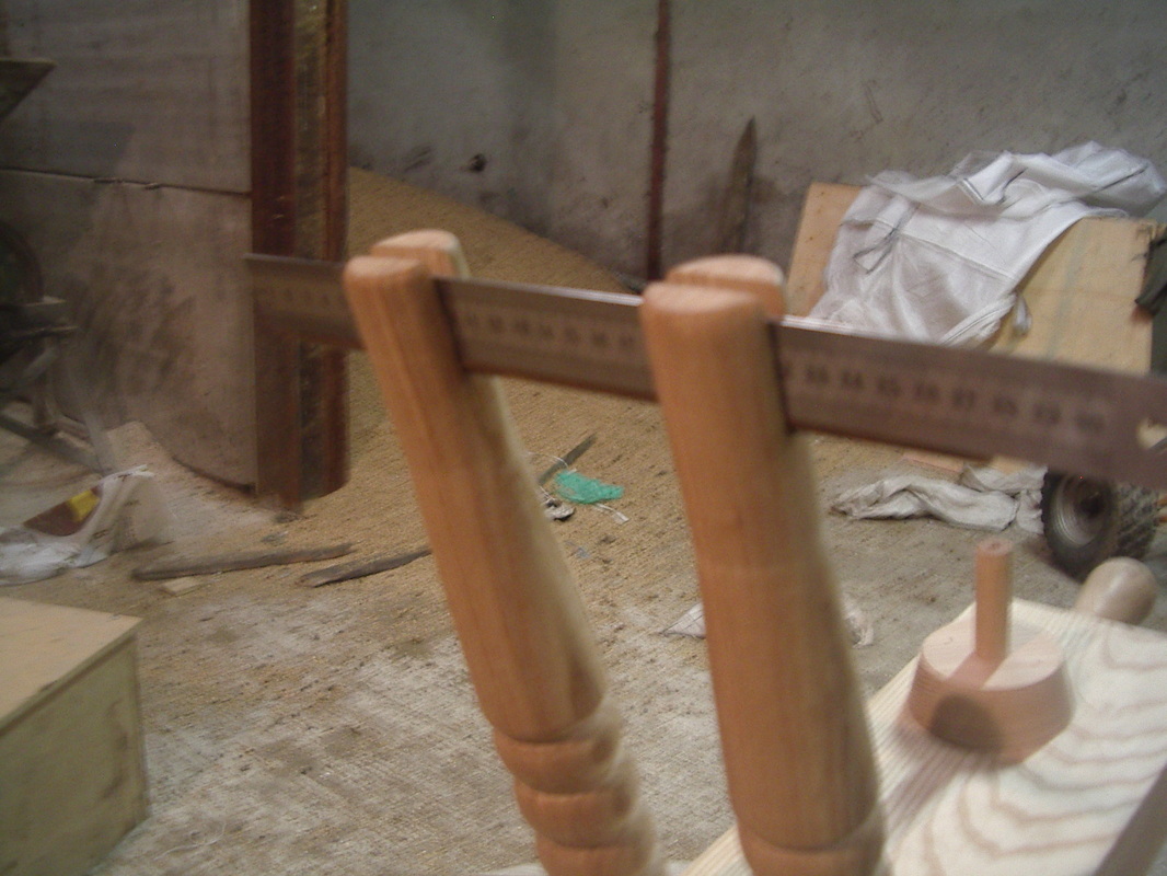
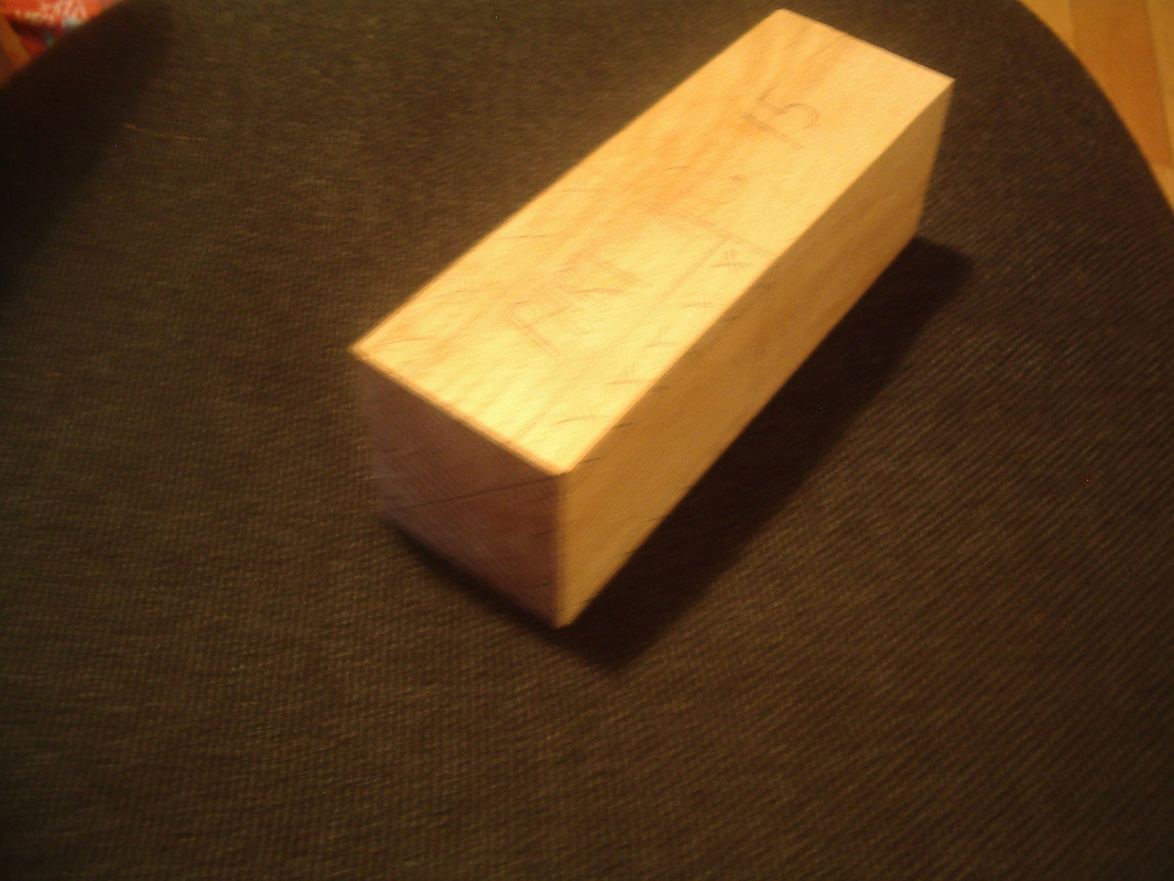
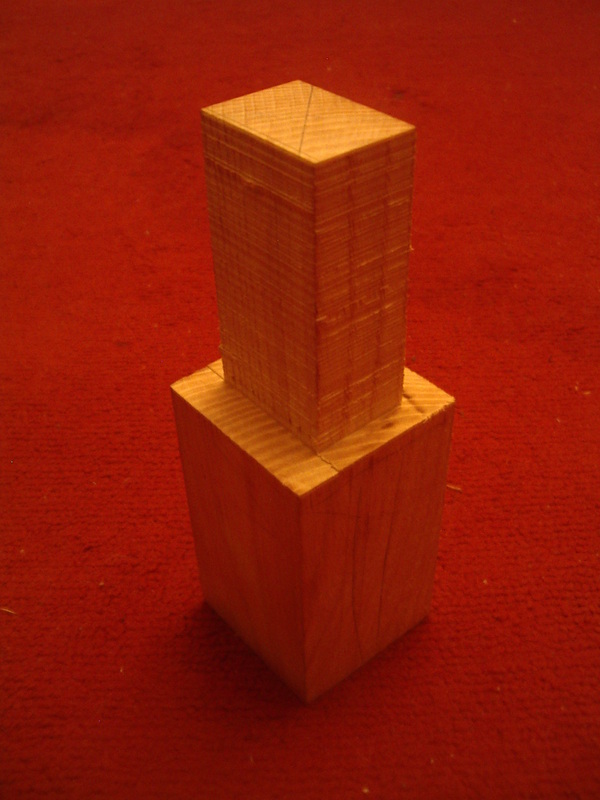
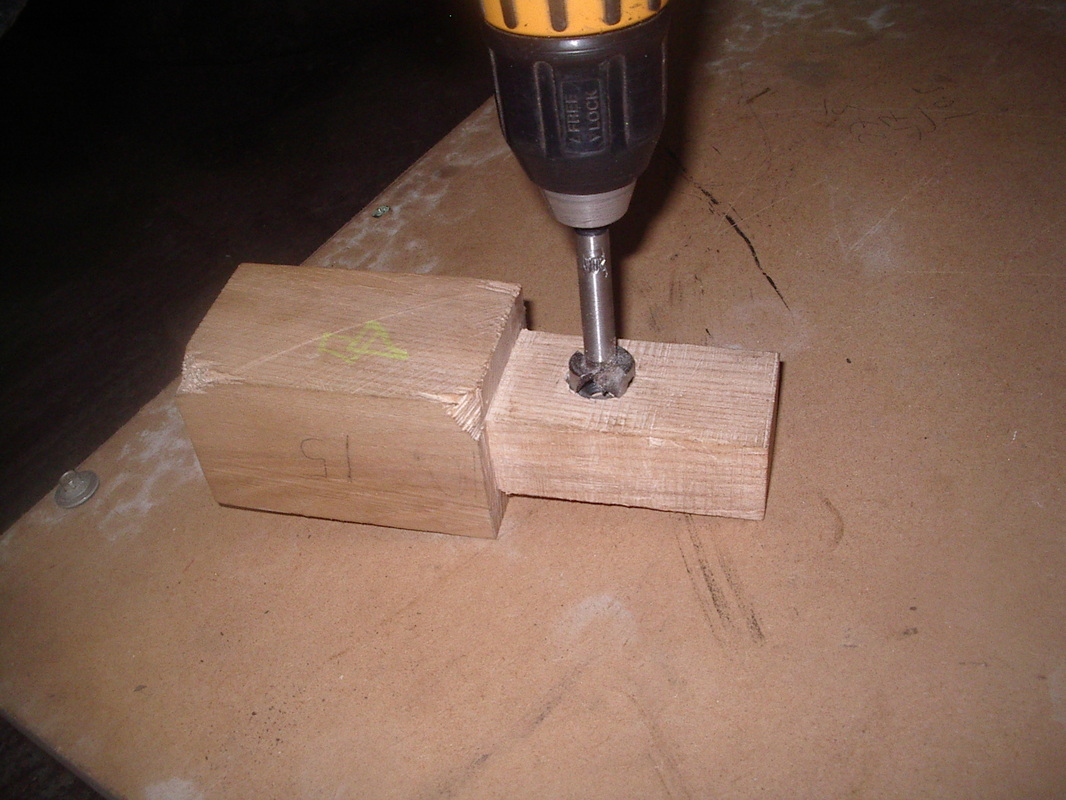
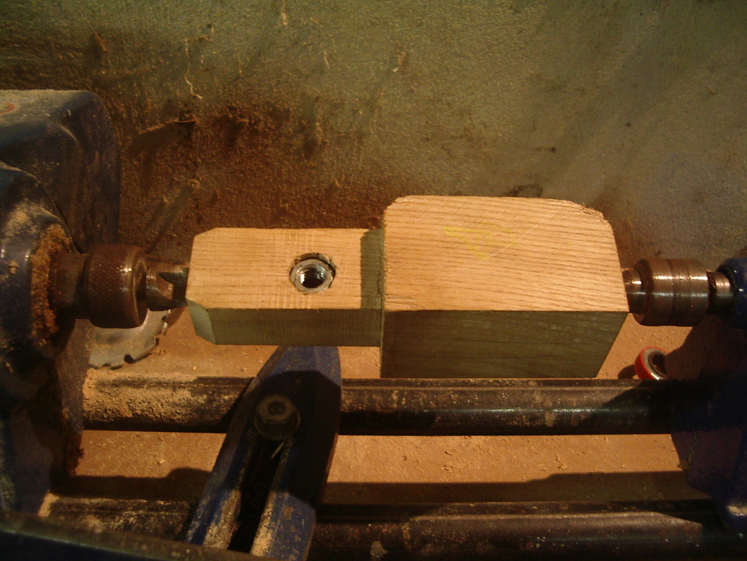
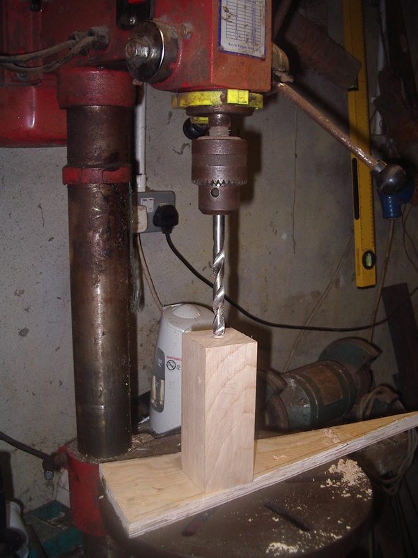
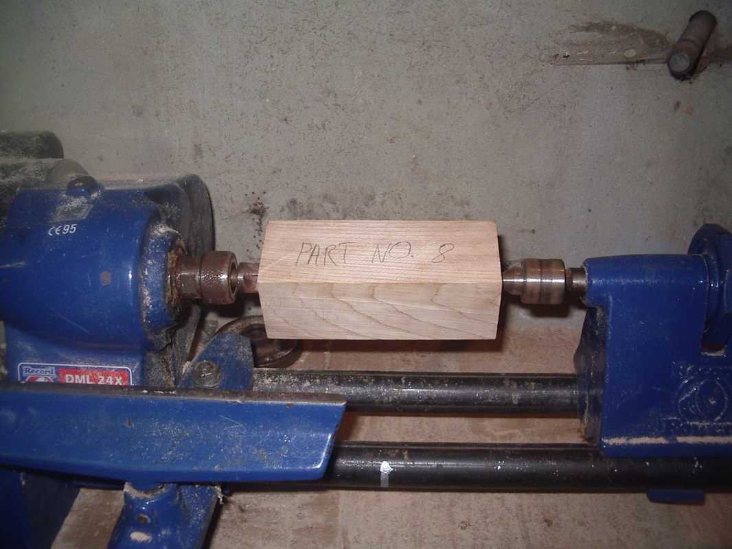
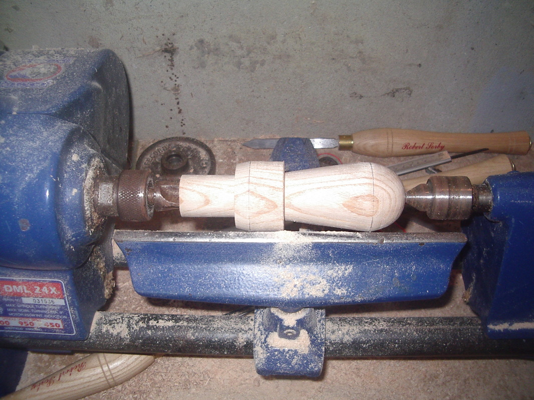
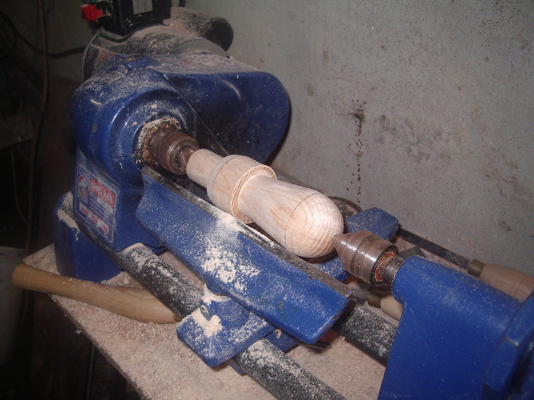
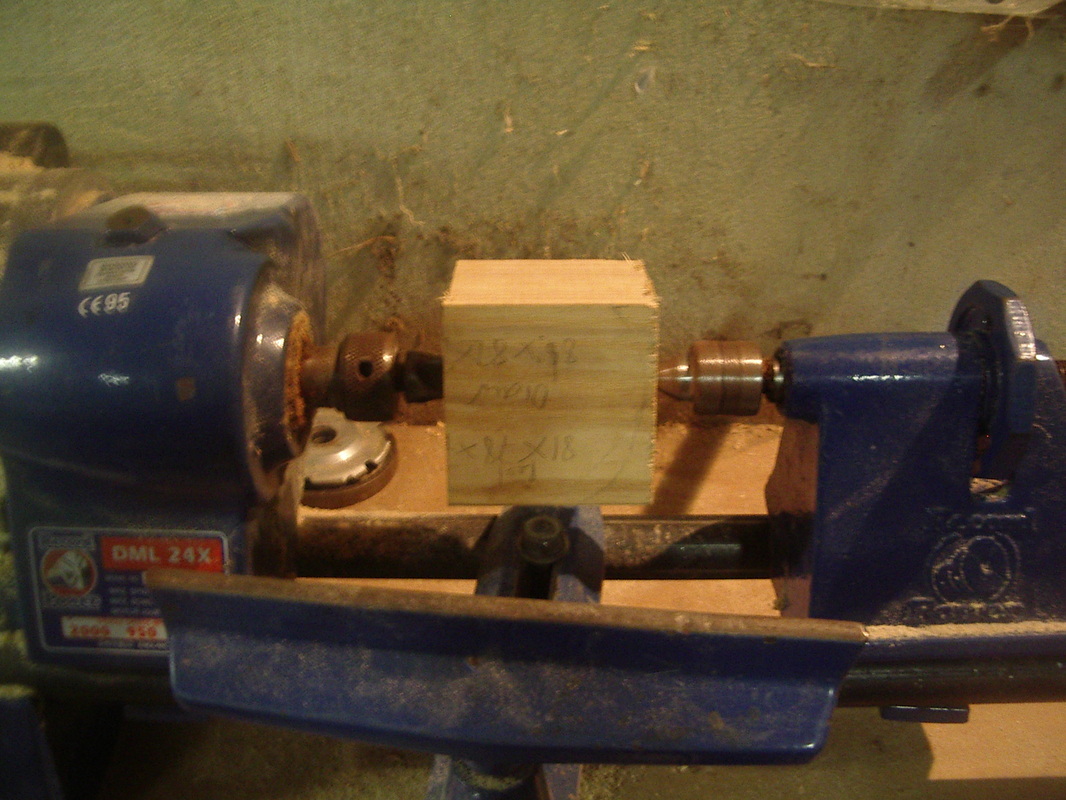
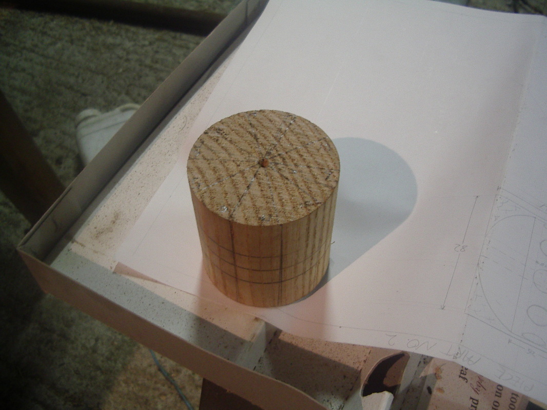
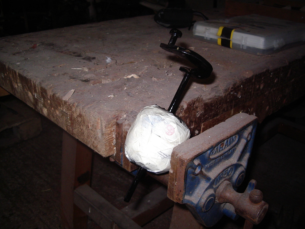
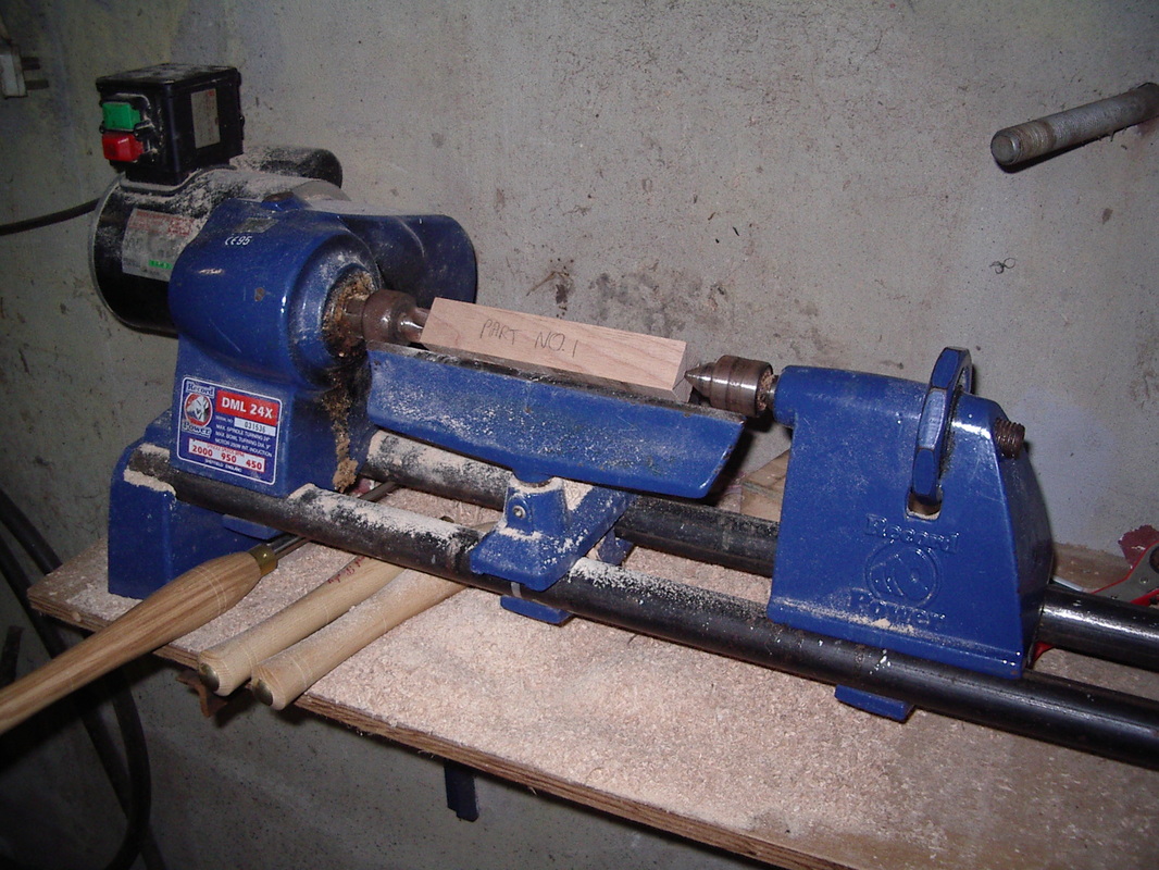
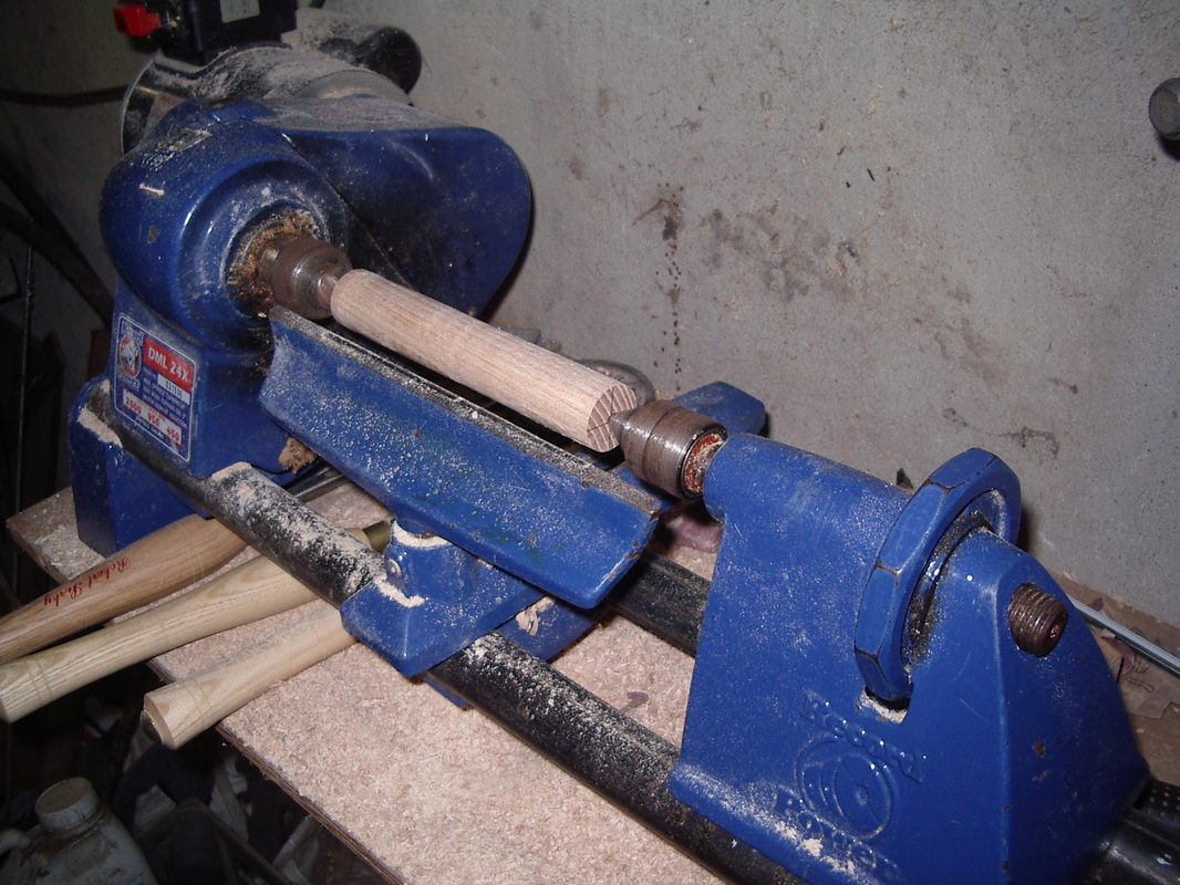
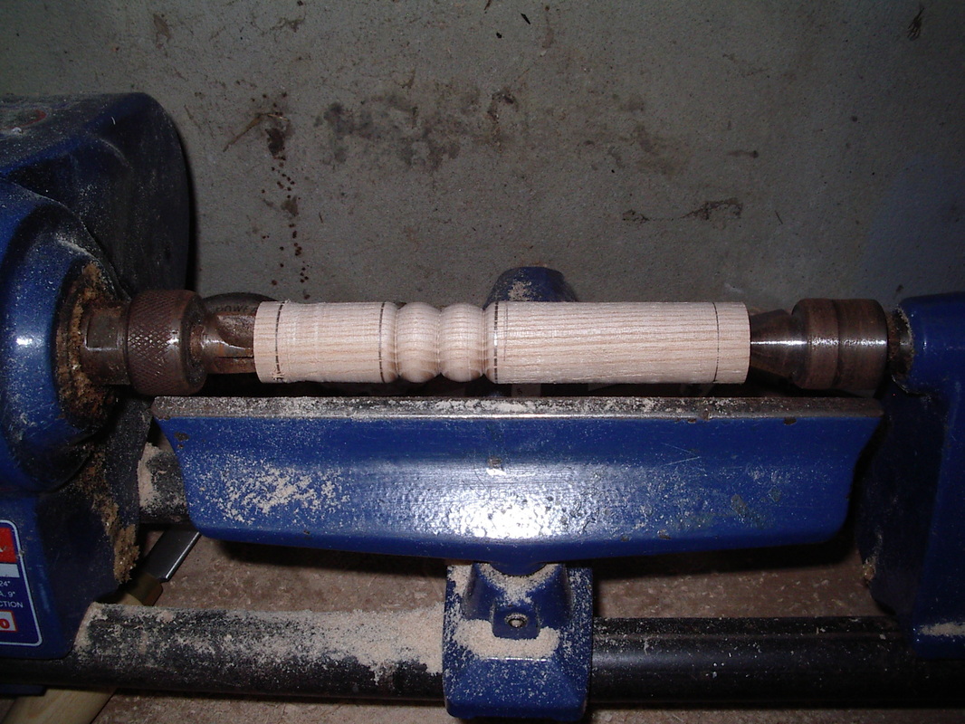
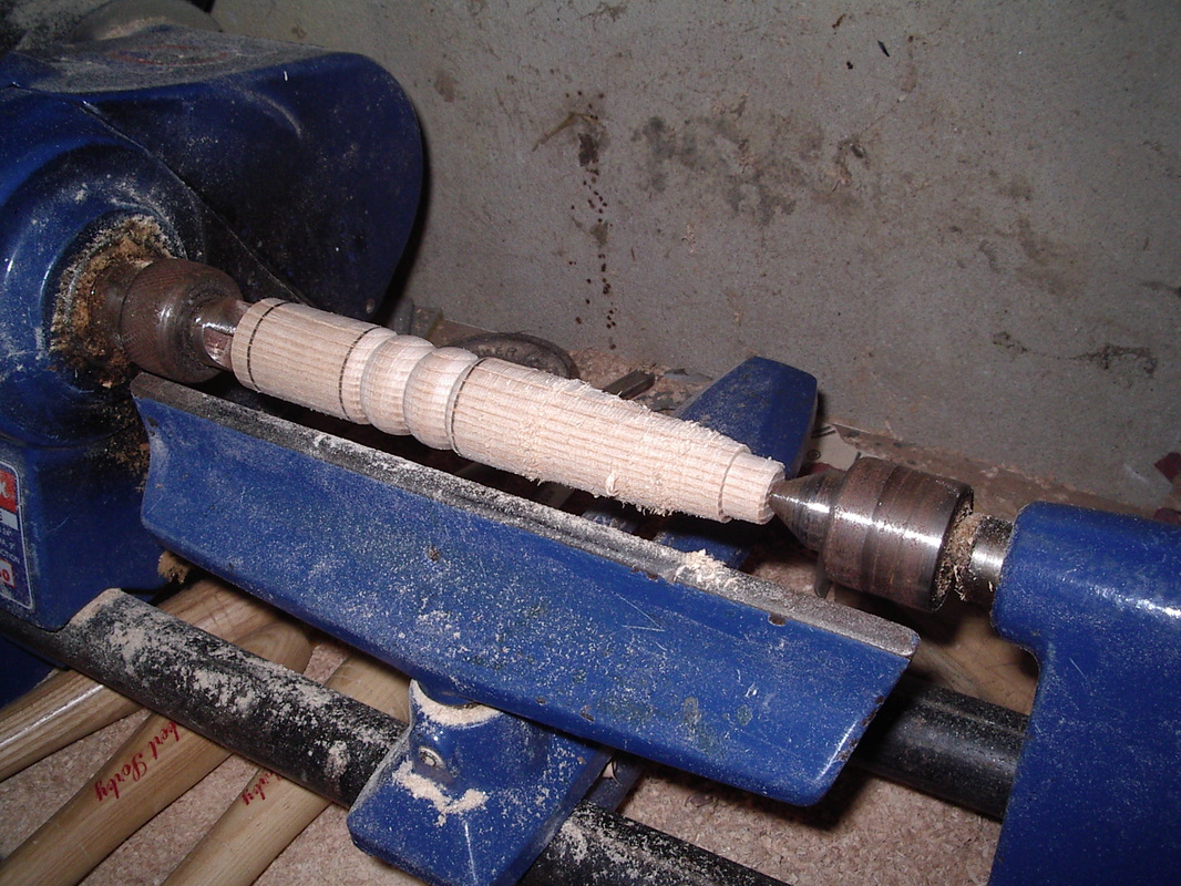
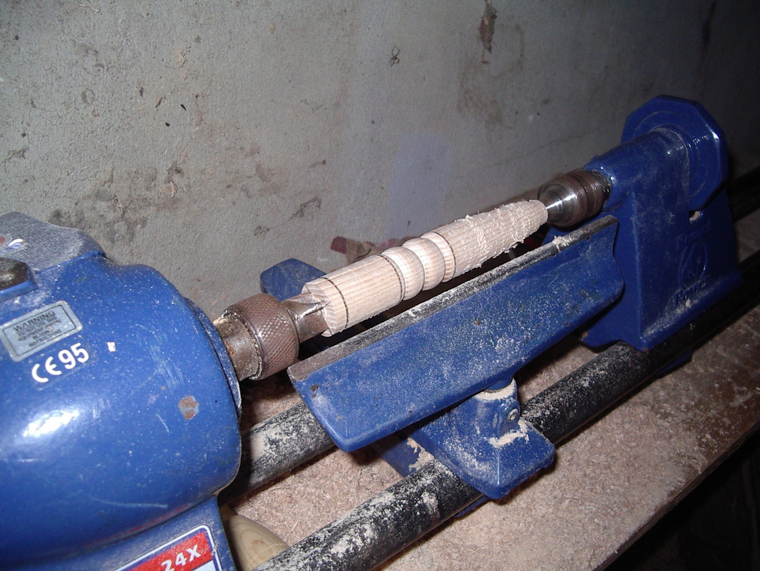
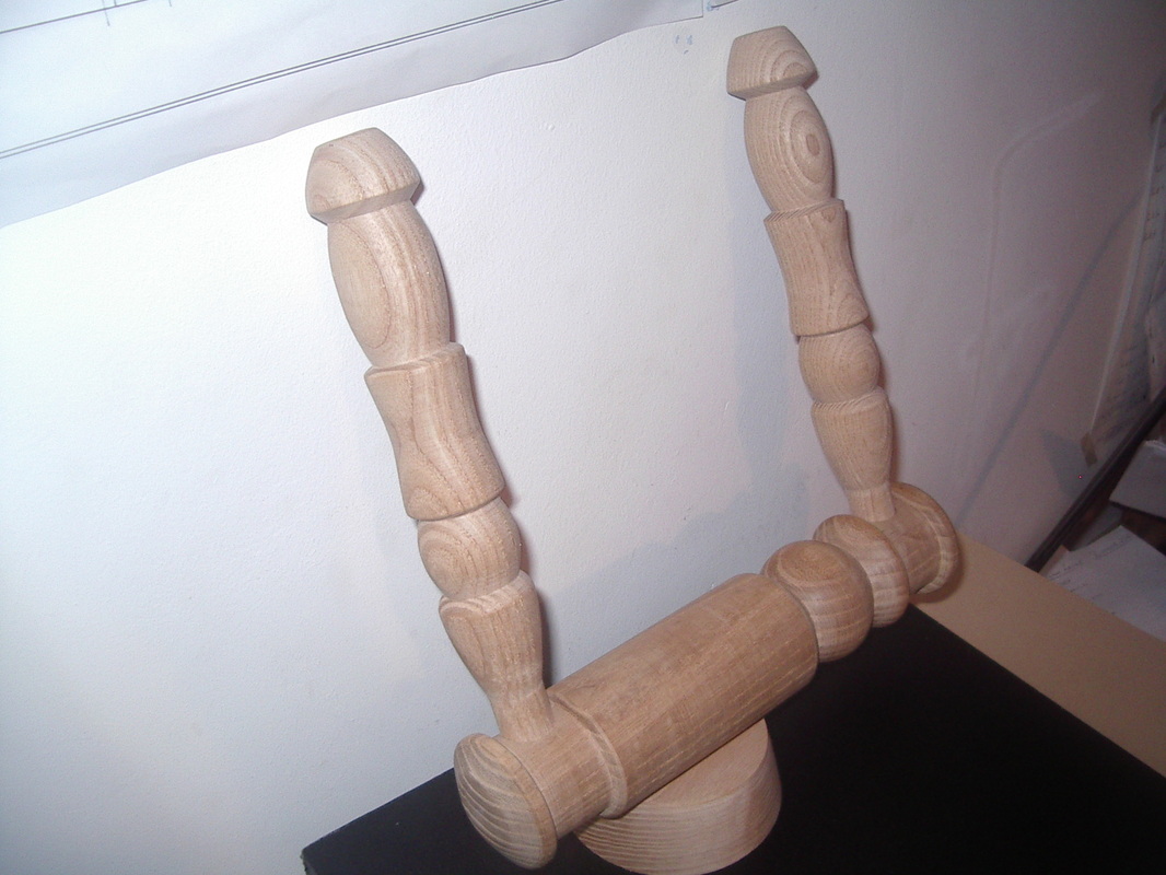
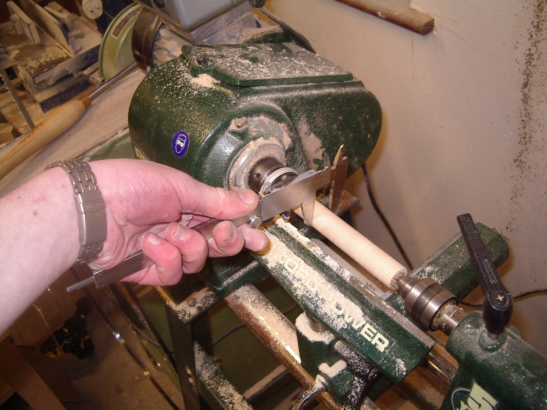
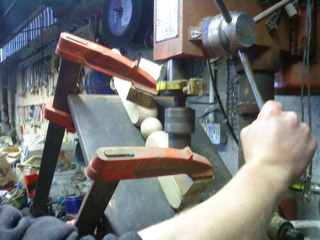
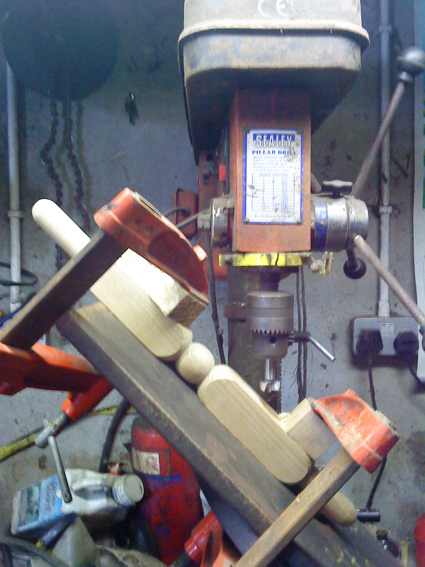
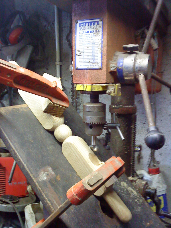
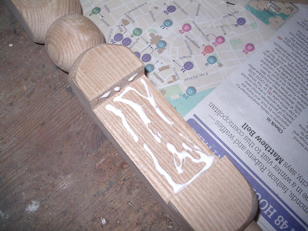
The Legs
Here is a photo-log of the steps followed when making the legs of the spinning wheel. The three legs are of the same shape.
Here is a photo-log of the steps followed when making the legs of the spinning wheel. The three legs are of the same shape.

The Wheel Supports
Here is a photo-log of the steps followed when making the Wheel Supports. The steps to making these two identical parts are very similar to that of the legs manufacture. The main difference is that there is a slot to be removed from the piece after turning.
Here is a photo-log of the steps followed when making the Wheel Supports. The steps to making these two identical parts are very similar to that of the legs manufacture. The main difference is that there is a slot to be removed from the piece after turning.
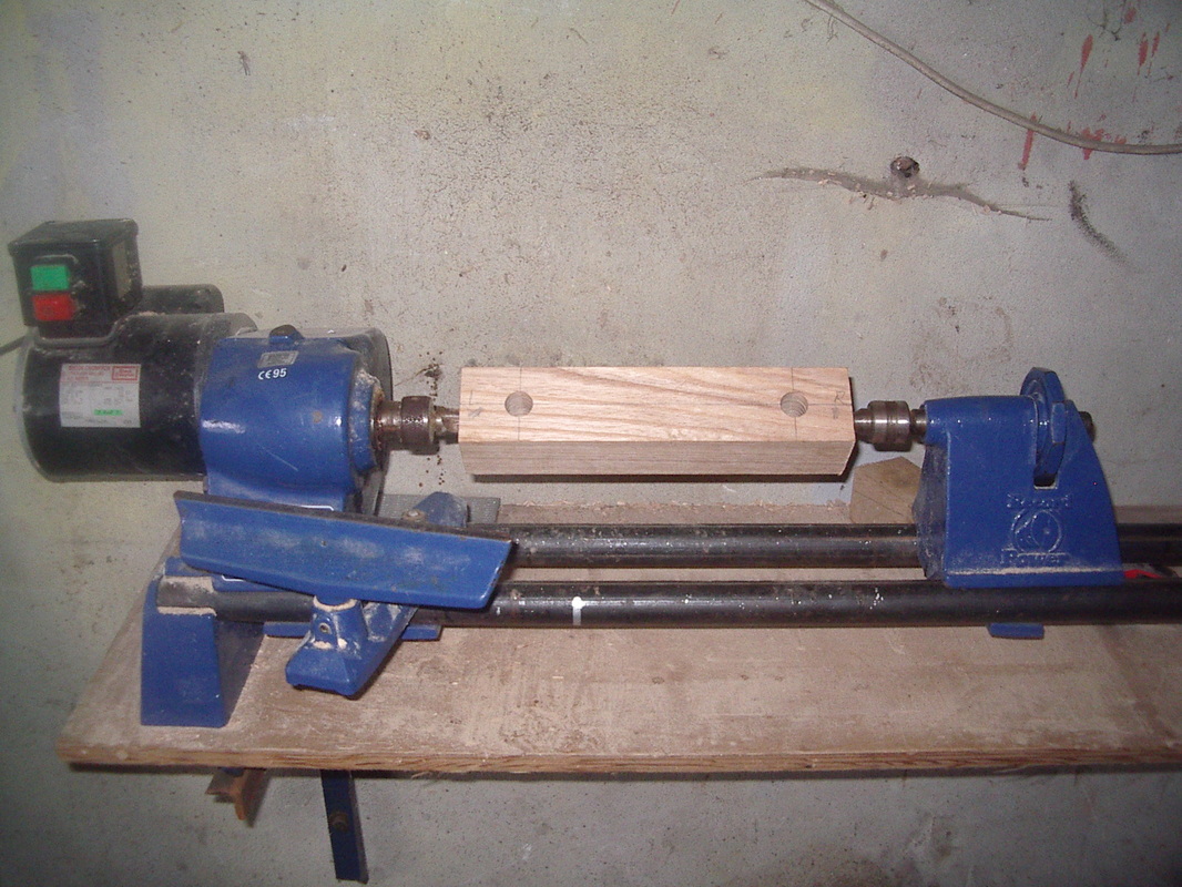
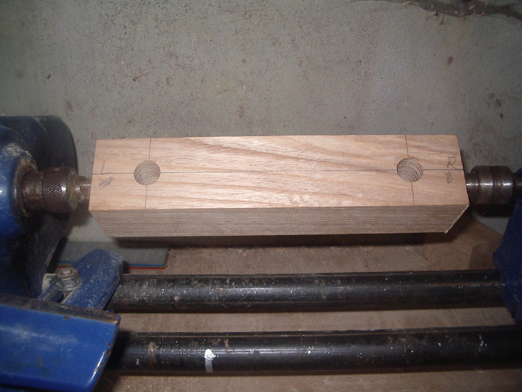
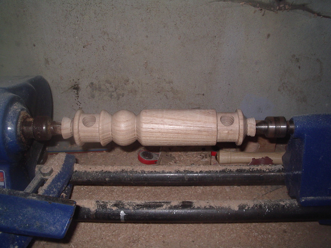
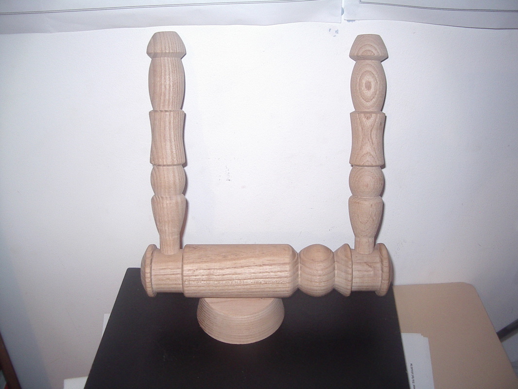
The Mother of All Support
Here is a photo-log of the steps followed when making the 'Mother of all support' which is the part that slides backwards and forwards through the rectangular hole in the base, which in turn enables the drive band to be tensioned
Here is a photo-log of the steps followed when making the 'Mother of all support' which is the part that slides backwards and forwards through the rectangular hole in the base, which in turn enables the drive band to be tensioned
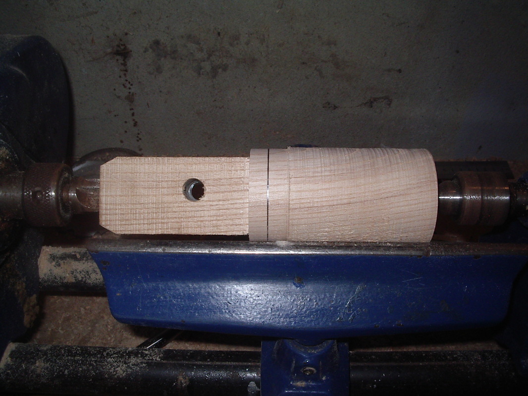
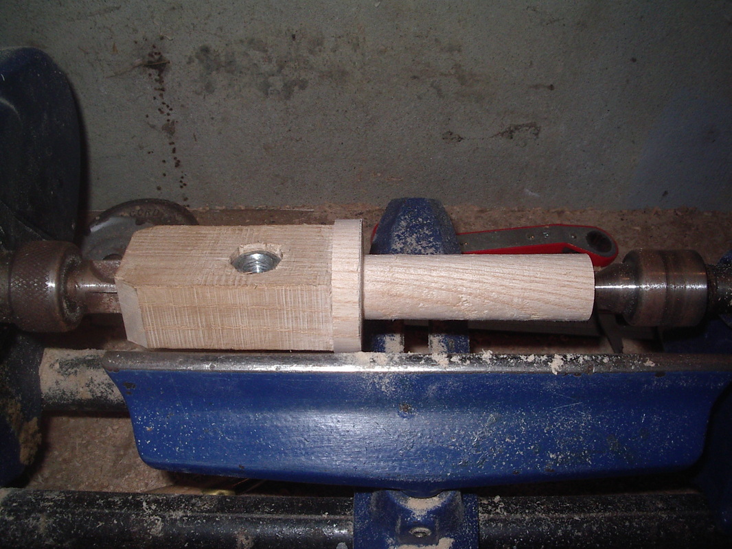
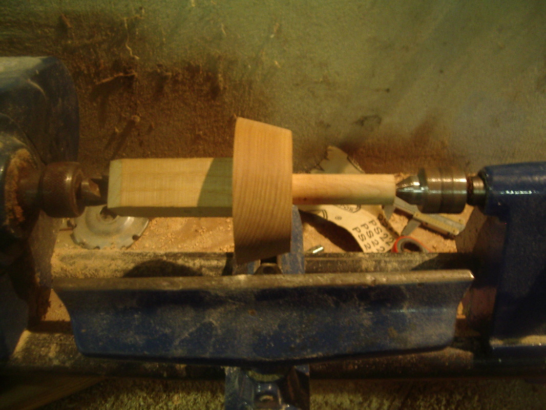
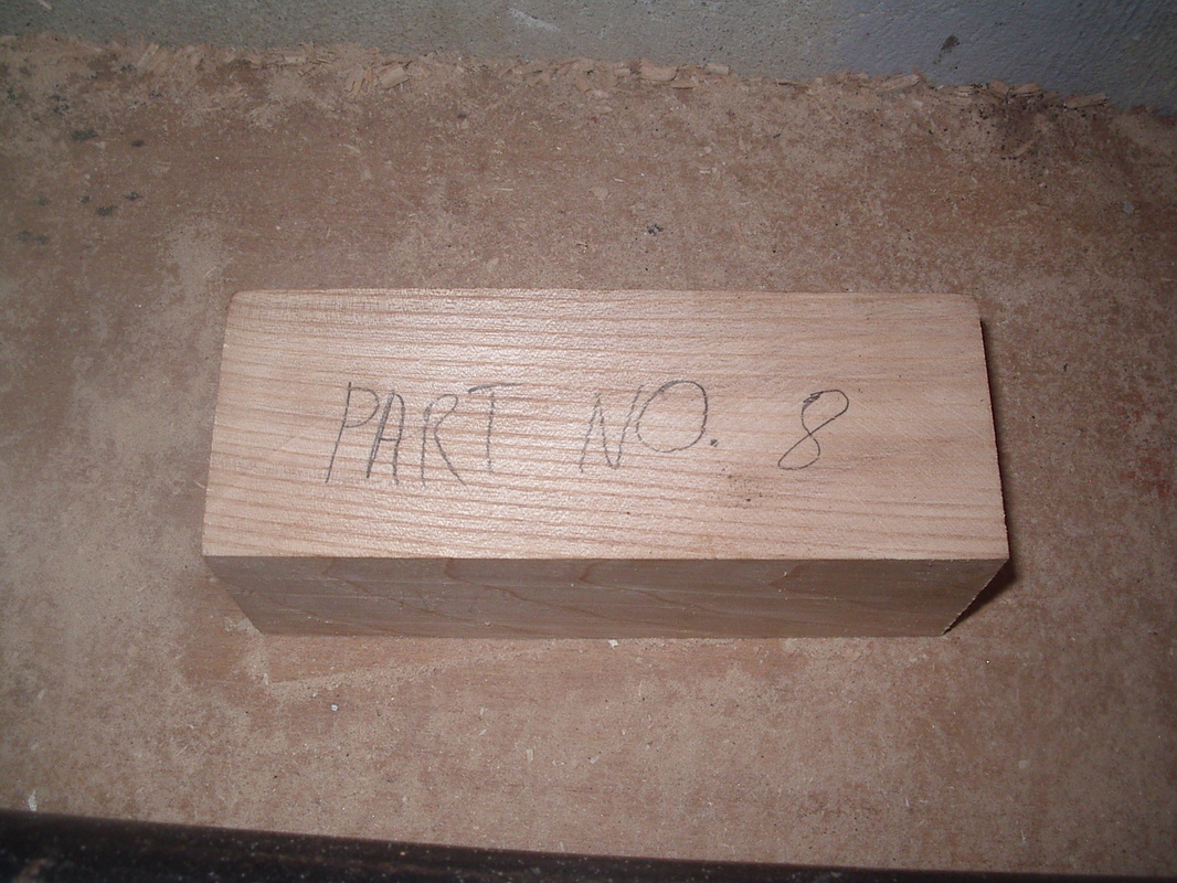
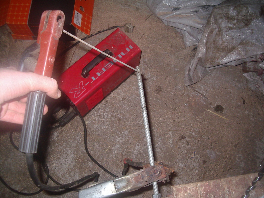
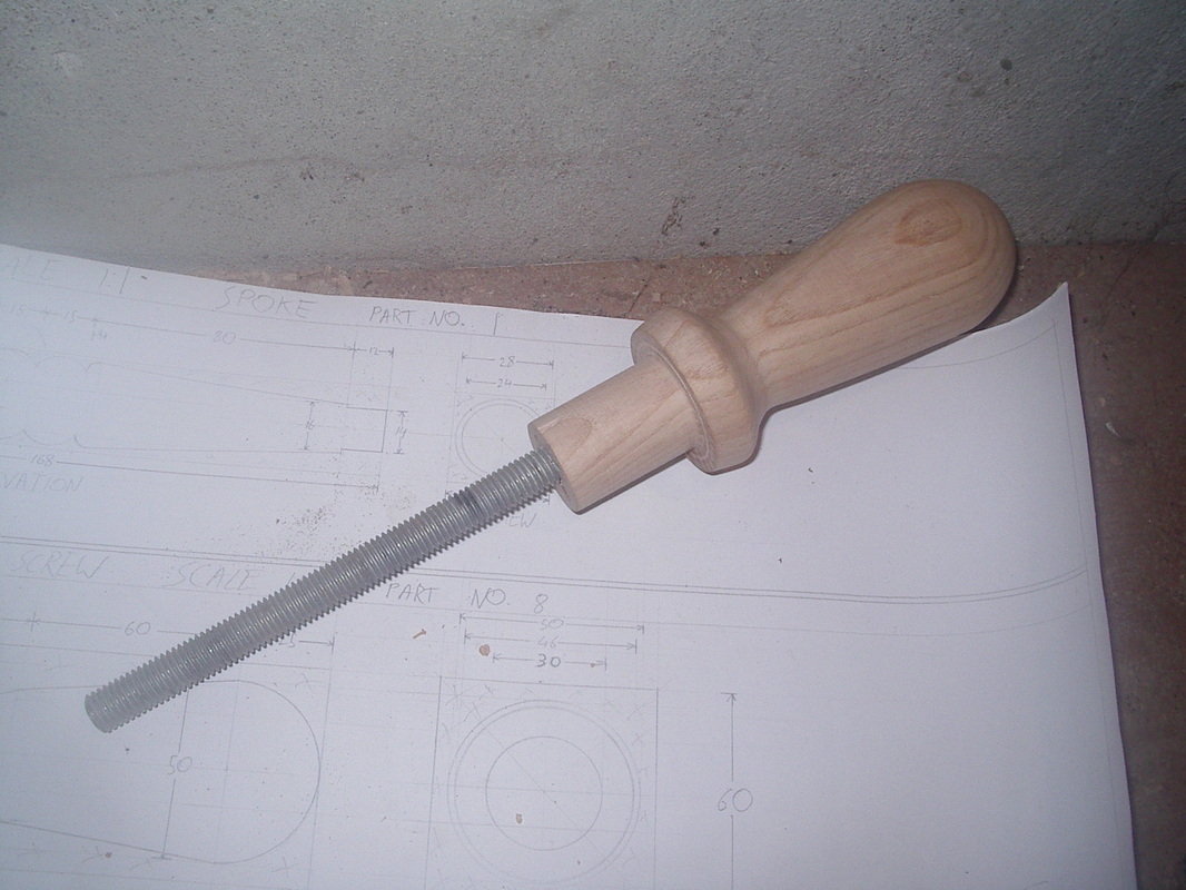
The Tension Adjustment Screw
Here is a photo-log of the steps followed when making the Tension Adjustment Screw. The piece is turned and then a threaded bar is inserted.
Here is a photo-log of the steps followed when making the Tension Adjustment Screw. The piece is turned and then a threaded bar is inserted.
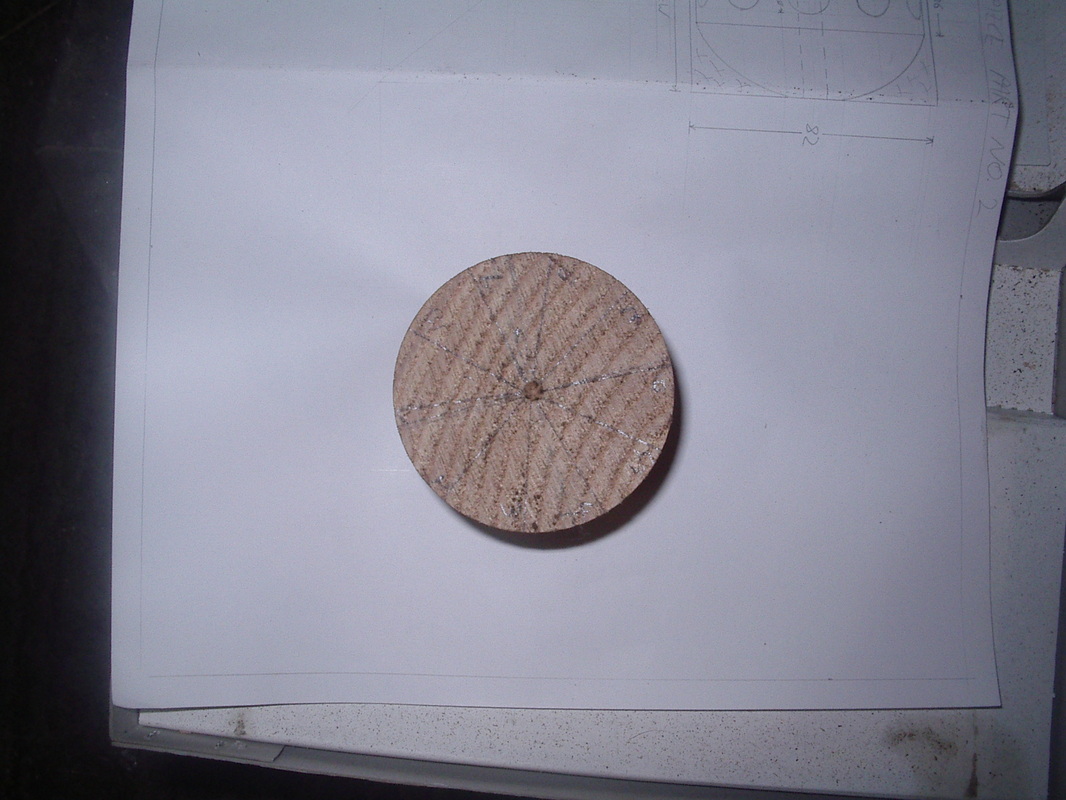
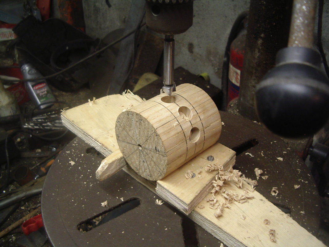
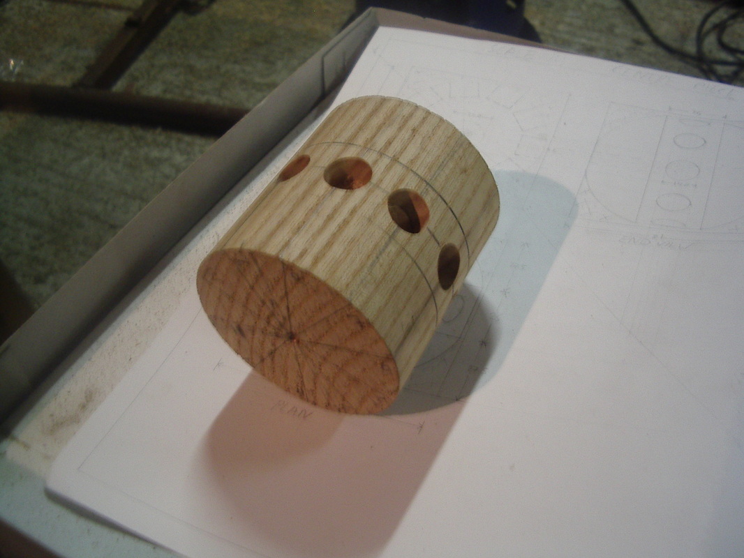
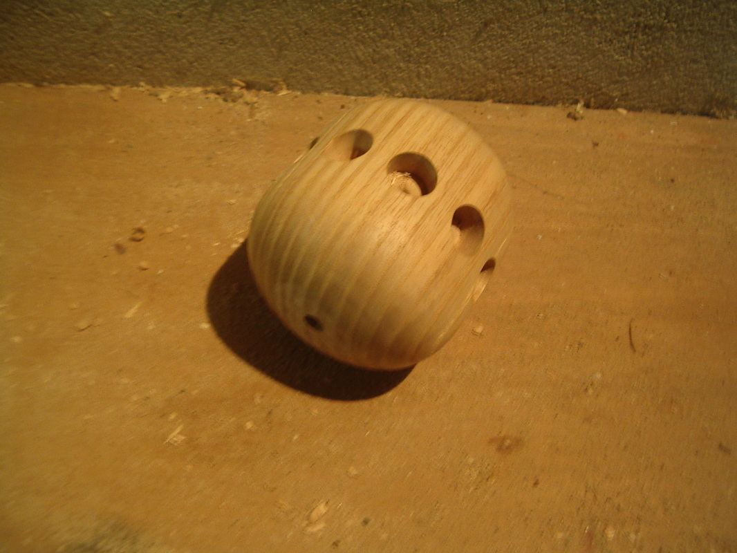
The Wheel Hub
Here is a photo-log of the steps followed when making the Hub for the centre of the wheel. The piece will fit ten spokes.
Here is a photo-log of the steps followed when making the Hub for the centre of the wheel. The piece will fit ten spokes.
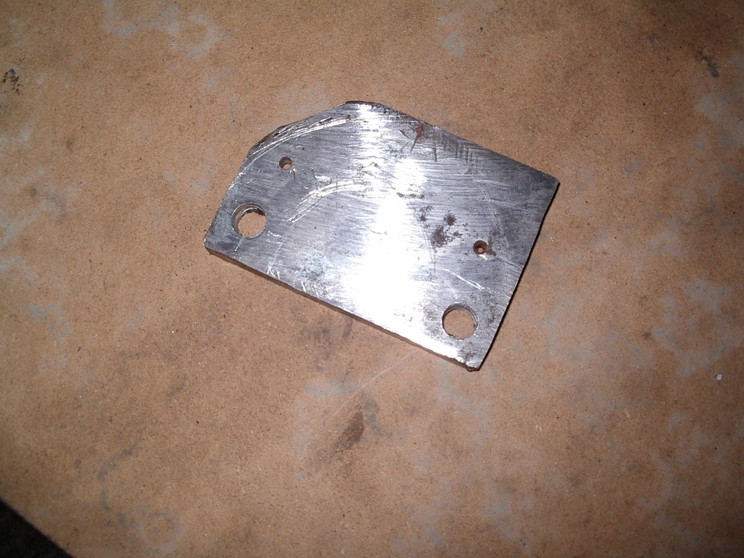
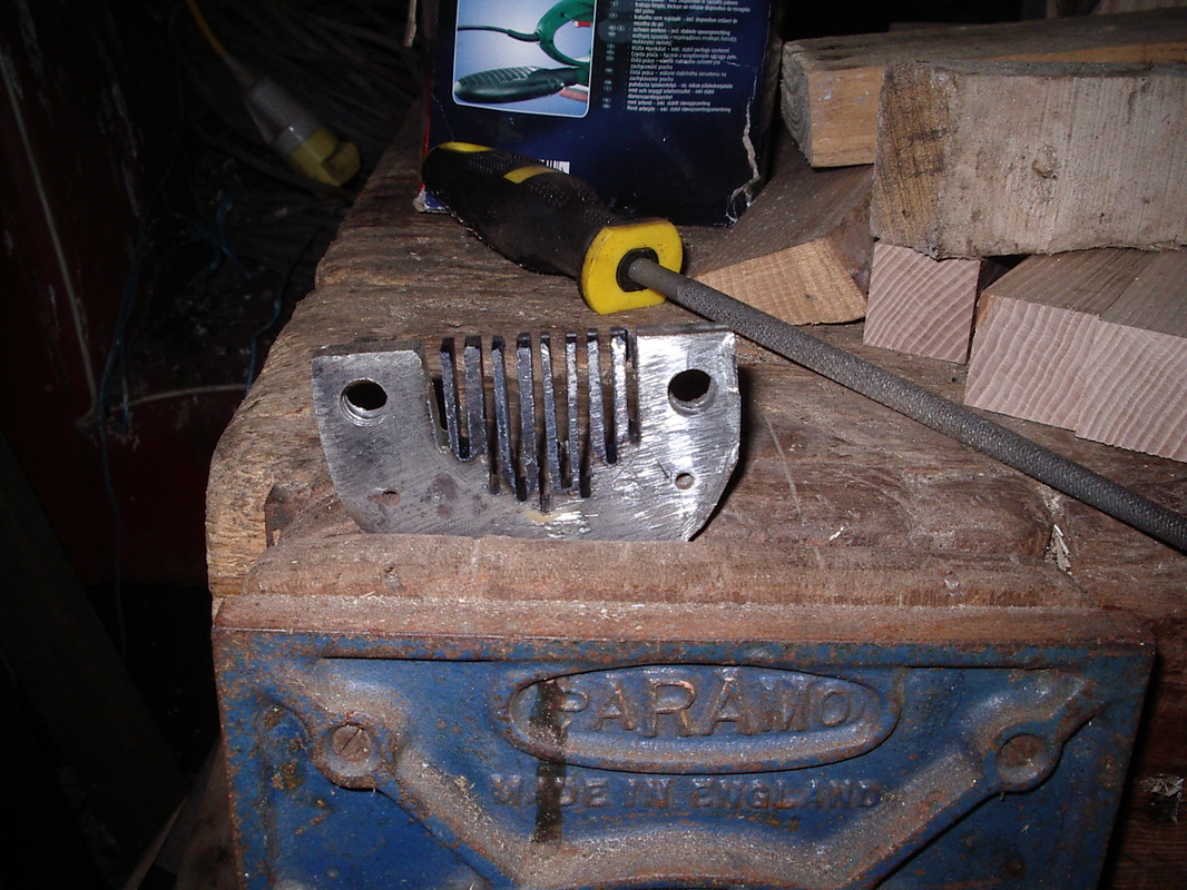
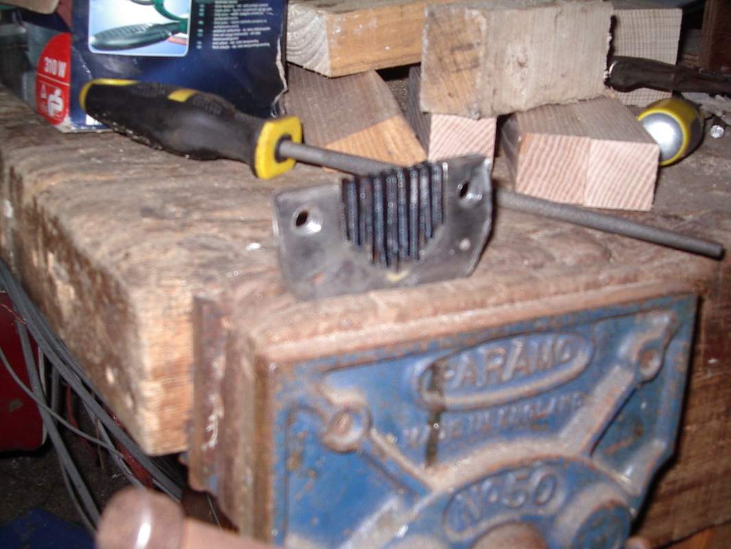
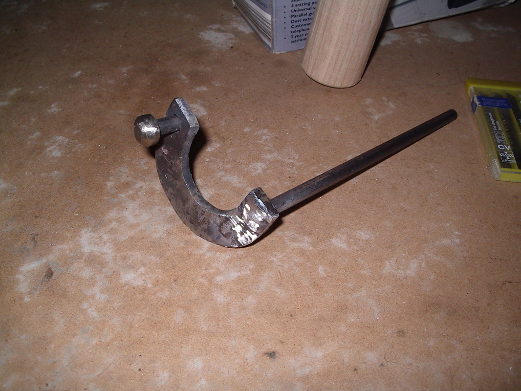
The Axle and Crank
Here is a photo-log of the steps followed when making the wheel axle and crank. It is made from bright mild steel and the four separate parts are welded together.
Here is a photo-log of the steps followed when making the wheel axle and crank. It is made from bright mild steel and the four separate parts are welded together.
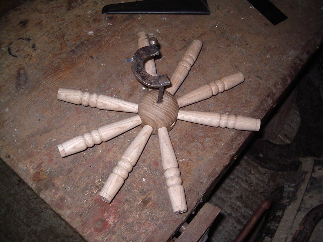
The Wheel Spokes
Here is a photo-log of the steps followed when making the Spokes for the wheel. There are ten spokes in this wheel.
Here is a photo-log of the steps followed when making the Spokes for the wheel. There are ten spokes in this wheel.
The Mother of All and the Maidens
Here is a photo-log of the steps followed when making the Mother of All and the Maidens. These are three separate parts. The maidens must fit tightly into the holes in the Mother of All as they cannot be glued because the maidens must swivel in order to change the bobbin.
Here is a photo-log of the steps followed when making the Mother of All and the Maidens. These are three separate parts. The maidens must fit tightly into the holes in the Mother of All as they cannot be glued because the maidens must swivel in order to change the bobbin.
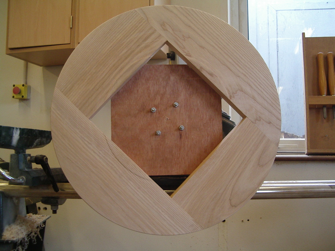
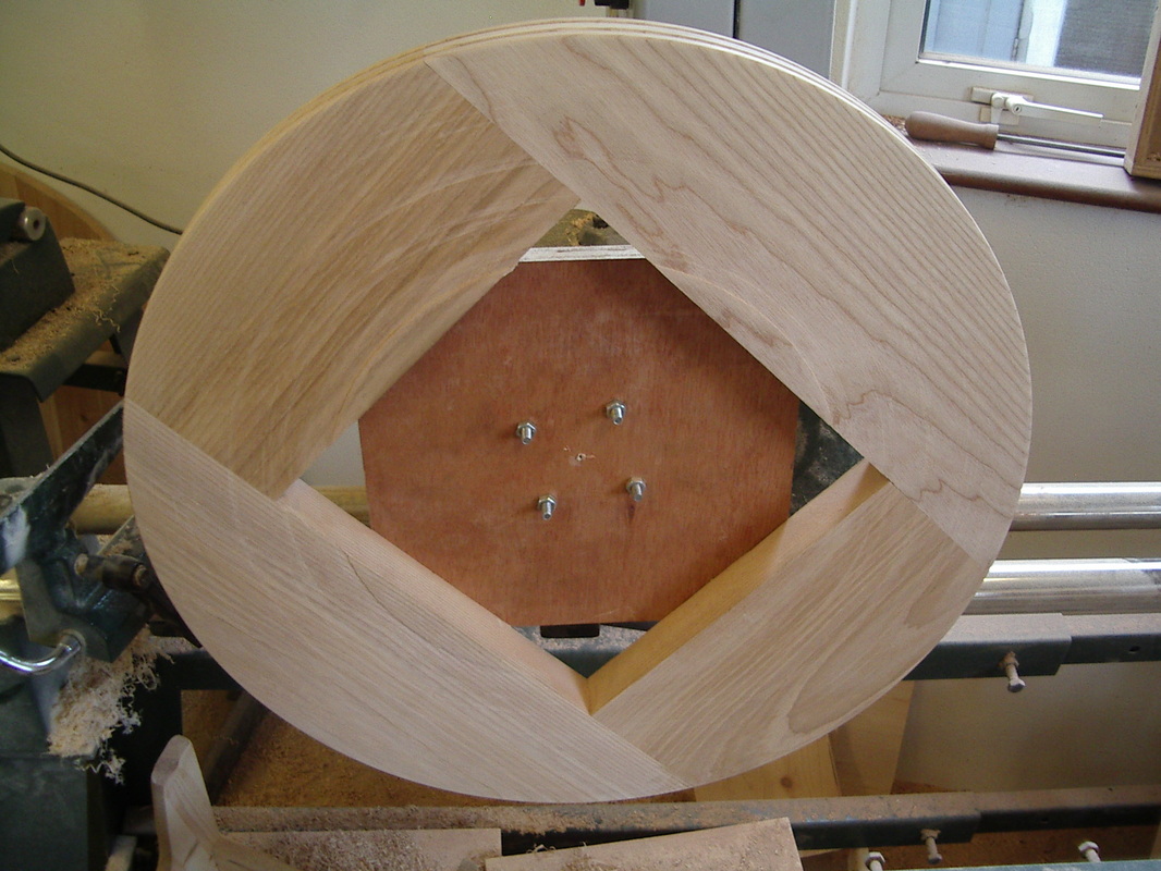
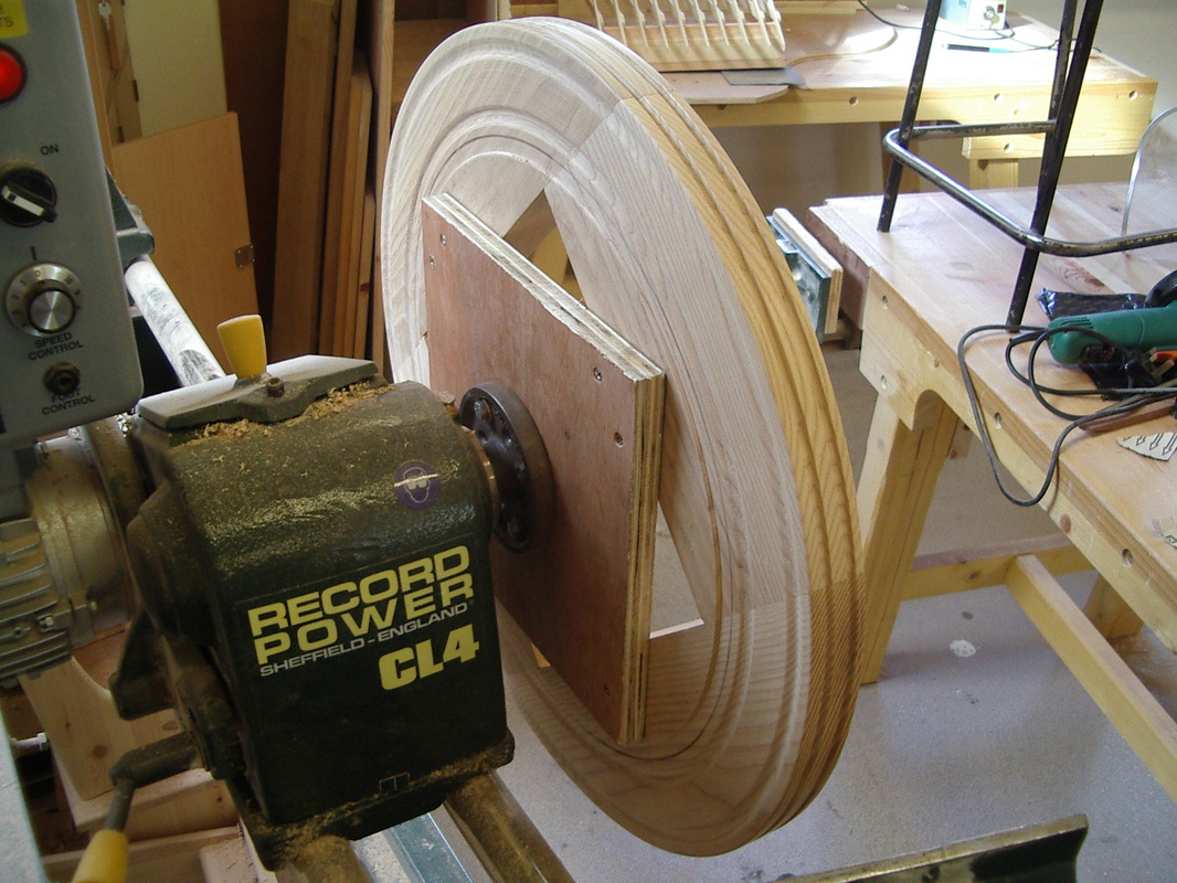
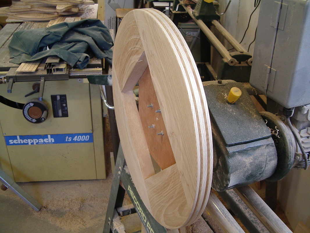
The Wheel Rim
Here is a photo-log of the steps followed when making the Mother of All and the Maidens. The wheel rim is made of four separate parts which are joined together using biscuit joints. Eight biscuits are used in total, two at each end of the short pieces. The wheel rim is turned using the face plate and after the other side diameter and two faces are finished the lathe speed is turned down and the inside diameter is cut through until the wheel rim becomes separated from the lathe.
Here is a photo-log of the steps followed when making the Mother of All and the Maidens. The wheel rim is made of four separate parts which are joined together using biscuit joints. Eight biscuits are used in total, two at each end of the short pieces. The wheel rim is turned using the face plate and after the other side diameter and two faces are finished the lathe speed is turned down and the inside diameter is cut through until the wheel rim becomes separated from the lathe.
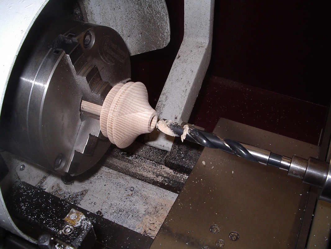
The Bobbin
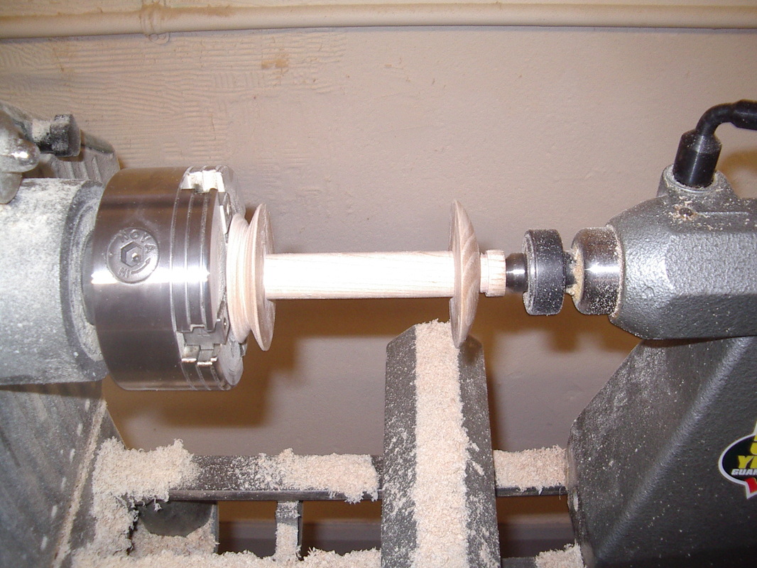
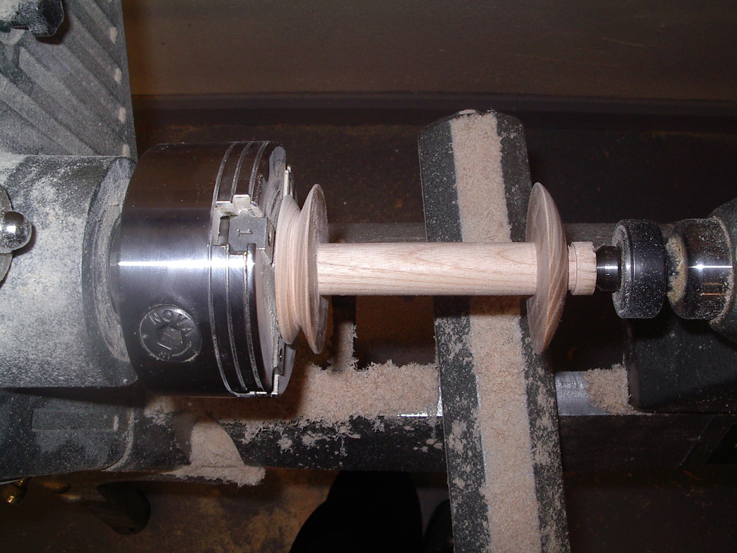
Here is a photo-log of the steps followed when making the Bobbin. This function of this part is to collect the wool thread after spinning. The bobbin is made from three separate parts which are joined using glue.
Here is a photo-log of the steps followed when making the Bobbin. This function of this part is to collect the wool thread after spinning. The bobbin is made from three separate parts which are joined using glue.


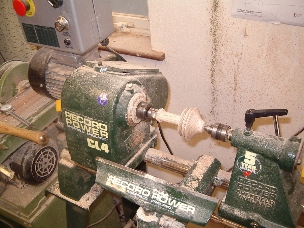
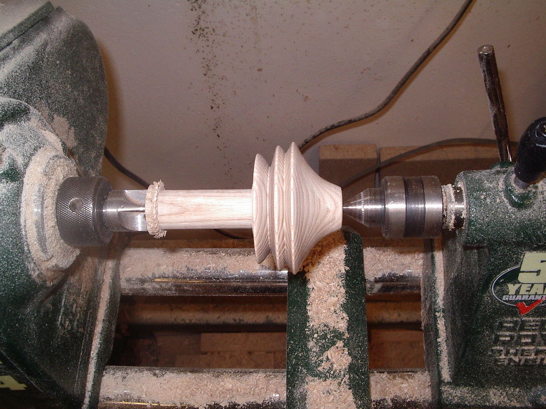
The Pulley
Here is a photo-log of the steps followed when making the Pulley. The Pulley has quite a large diameter so three pieces were glued together for this part. A left-hand threaded nut is required for the pulley, this is created from a centre drilled piece of hexagonal brass bar and the hole is tapped using left-hand tap. This nut is then glued into the end of the turned pulley. Waste cut off the piece at the end using tenon saw.
Here is a photo-log of the steps followed when making the Pulley. The Pulley has quite a large diameter so three pieces were glued together for this part. A left-hand threaded nut is required for the pulley, this is created from a centre drilled piece of hexagonal brass bar and the hole is tapped using left-hand tap. This nut is then glued into the end of the turned pulley. Waste cut off the piece at the end using tenon saw.
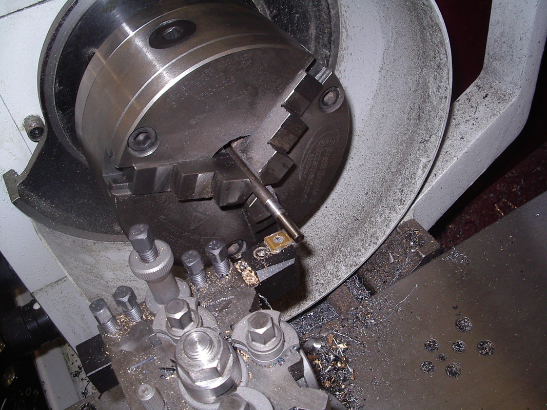
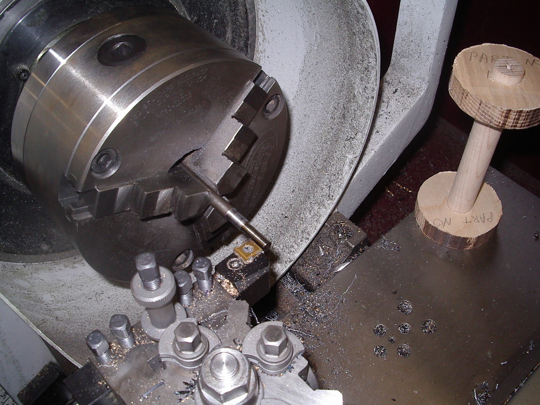
The Flyer Axle
Here is a photo-log of the steps followed when making the Flyer Axle. This part is made from bright mild steel round bar. The end is turned down to size and a left-hand thread is cut using a left hand die. A separate piece for the other end is made from larger diameter round bar and welded to the axle.
Here is a photo-log of the steps followed when making the Flyer Axle. This part is made from bright mild steel round bar. The end is turned down to size and a left-hand thread is cut using a left hand die. A separate piece for the other end is made from larger diameter round bar and welded to the axle.
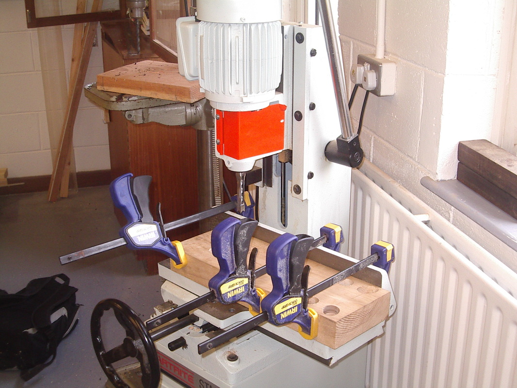
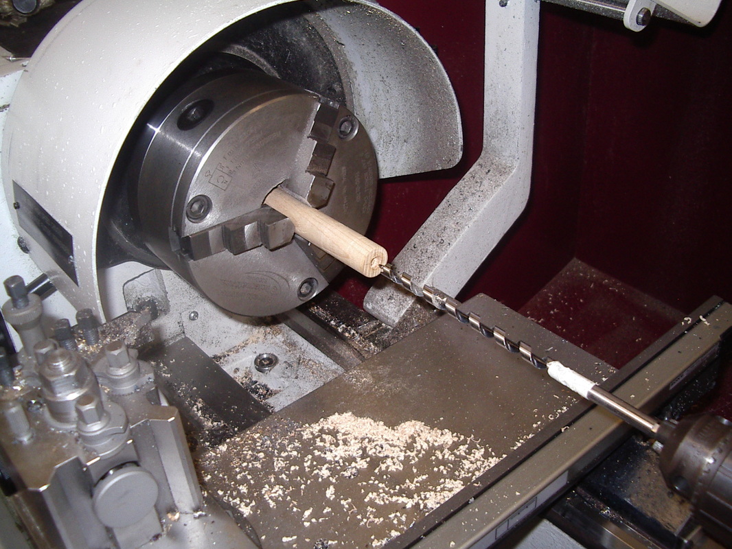
The Pedal Cross Bar
Here is a photo-log of the steps followed when making the Cross bar for the Pedal. The function of this piece is to support the pedal which is used to rotate the wheel. The piece is turned on the lathe between the spindles and then a hole drilled at an angle of 45 degrees and a trench removed from the piece support the pedal.
Here is a photo-log of the steps followed when making the Cross bar for the Pedal. The function of this piece is to support the pedal which is used to rotate the wheel. The piece is turned on the lathe between the spindles and then a hole drilled at an angle of 45 degrees and a trench removed from the piece support the pedal.
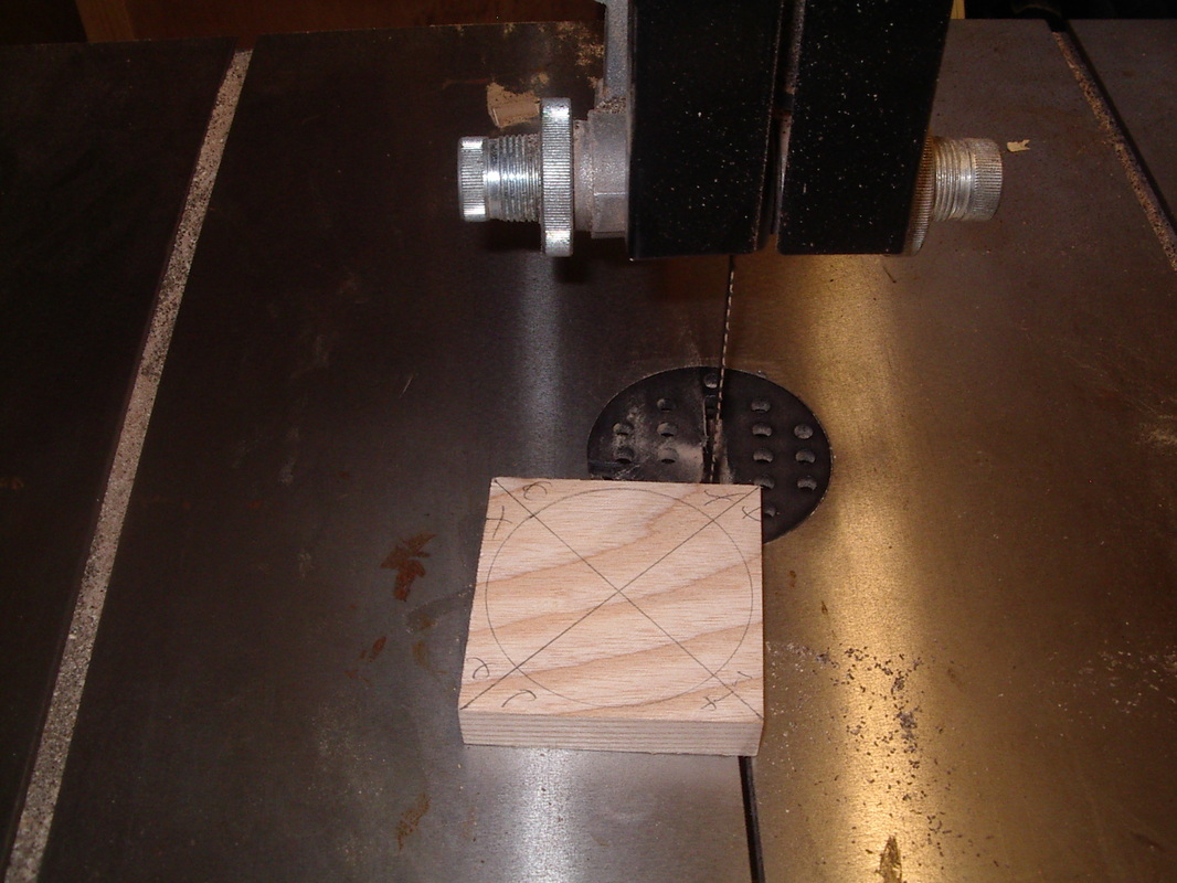
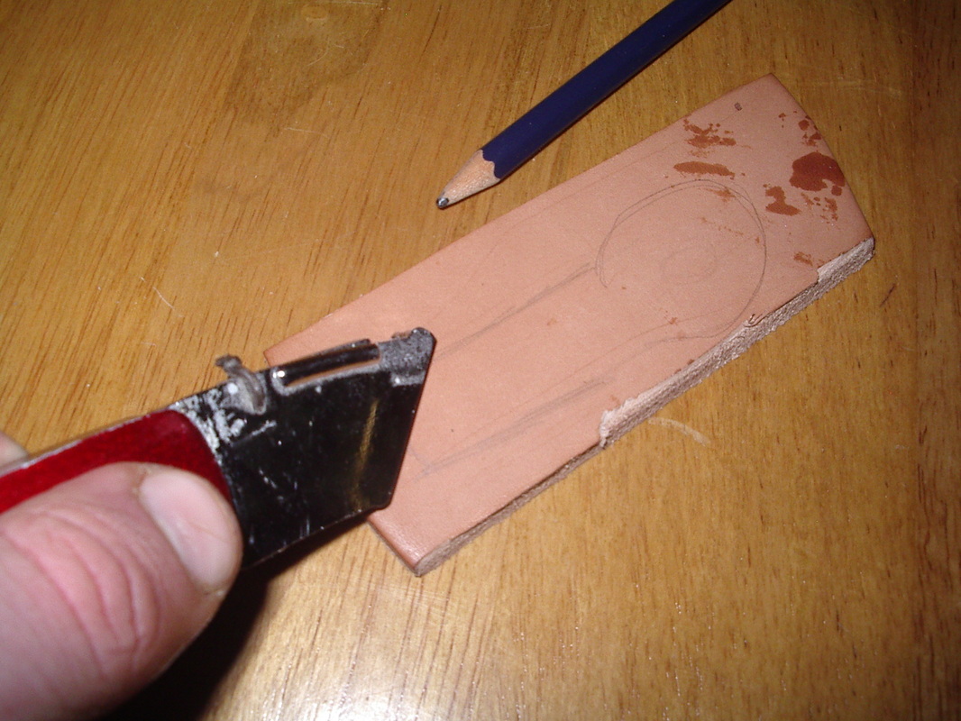
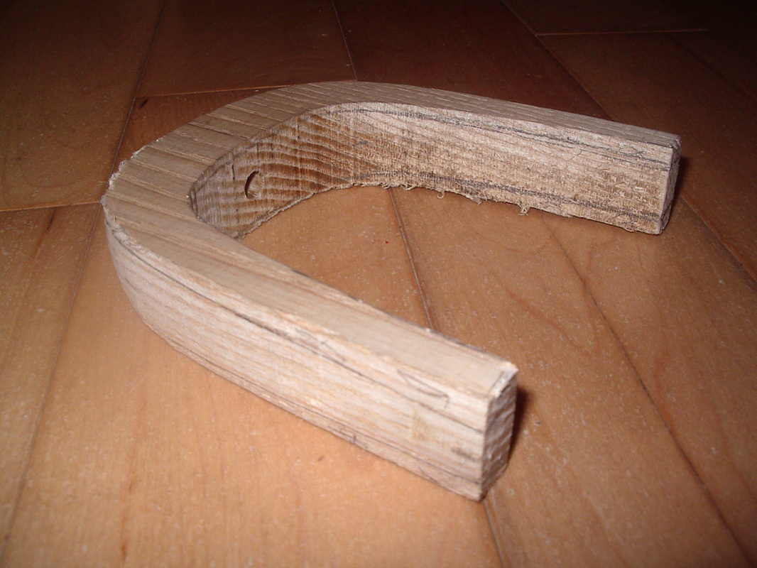
The Flyer
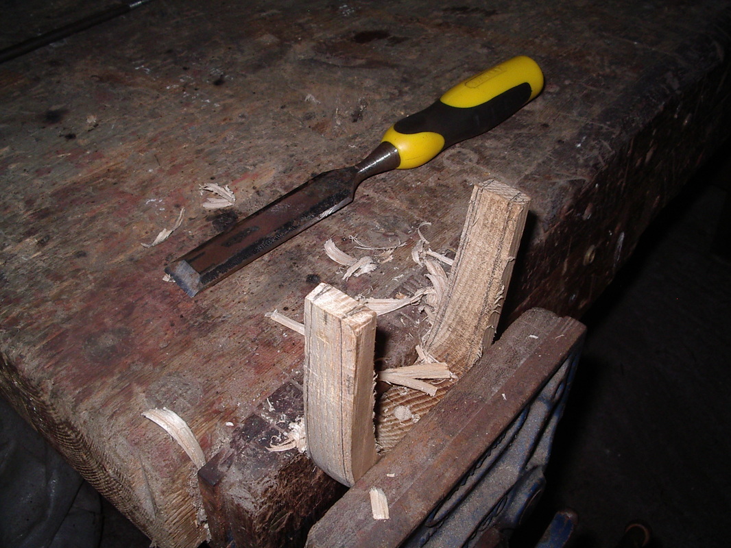
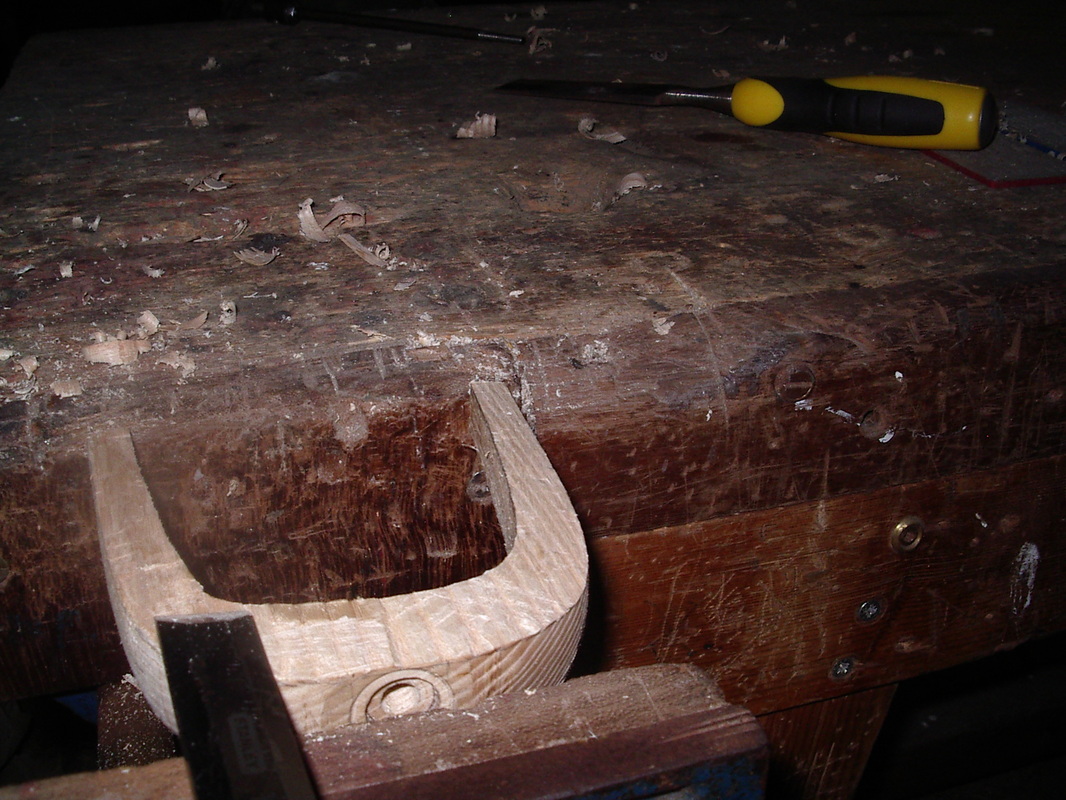
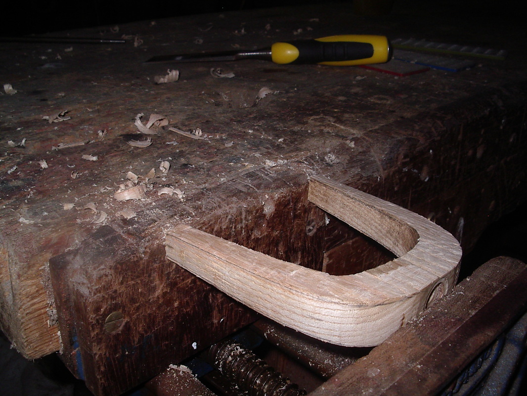
Here is a photo-log of the steps followed when making the Flyer. The function of this part is to position the the thread evenly across the full width of the bobbin during spinning. The flyer is first put on the lathe and the outside U-shape created then it is removed from lathe and the hole drilled on pillar drill. Next the inside U-shape is created by removing the waste using the bandsaw. Finally the piece is given its tapered shape by paring off waste with chisel.
Here is a photo-log of the steps followed when making the Flyer. The function of this part is to position the the thread evenly across the full width of the bobbin during spinning. The flyer is first put on the lathe and the outside U-shape created then it is removed from lathe and the hole drilled on pillar drill. Next the inside U-shape is created by removing the waste using the bandsaw. Finally the piece is given its tapered shape by paring off waste with chisel.
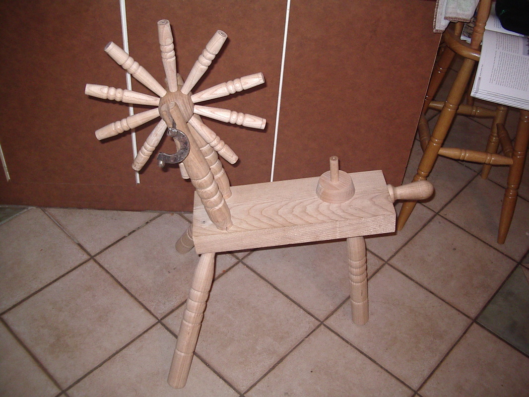
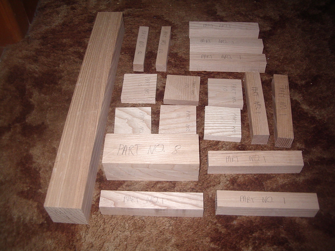
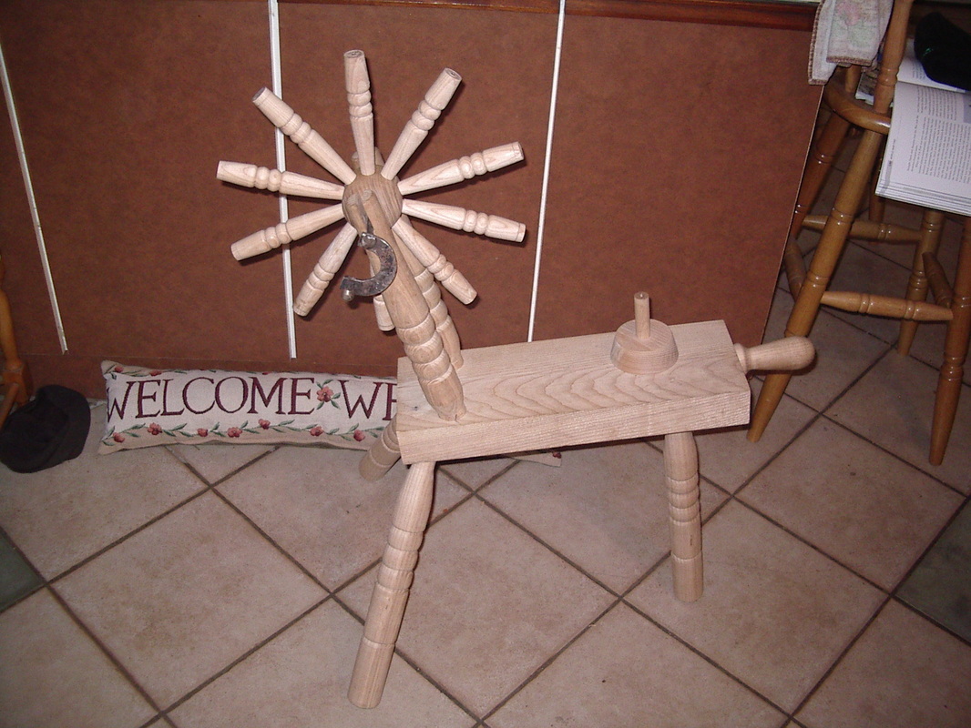
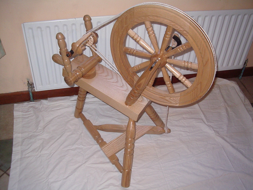
From Start to Finish
Here are some photos to recap on the steps followed when making this Spinning Wheel Project. There are quite a large number of separate parts in this project. Some parts are repeated but many are once-off pieces.
Here are some photos to recap on the steps followed when making this Spinning Wheel Project. There are quite a large number of separate parts in this project. Some parts are repeated but many are once-off pieces.

Below is a link to a website which sell fully dimensioned plans for several different types of Spinning Wheels. Please click on the link to visit this very useful website: